
Page 723 - Mechatronics with Experiments
P. 723
PROGRAMMABLE LOGIC CONTROLLERS 709
is hard-wired instead of programmed in the PLC. A hard-wired seal-in circuit includes the
following components:
1. a START button which is a momentary contact switch,
2. a STOP button,
3. a relay or starter coil from the output device (i.e., coil of a starter used to start a
motor)
When the START button makes a momentary contact, it energizes the coil of the relay
(or starter). Then the contacts from that coil maintain the flow of current since it is wired
in parallel with the START button even when the START button no longer makes contact
since it is a momentary button. The power flow is cutoff (stopped) any time the STOP
button is pressed. This is called the three-wire control. If for some reason the power is lost
to the circuit, the START button must be momentarily pressed again in order to start the
motor again. This is good for safety, but requires human intervention if the power flow in
the circuit is interrupted. In other words, the re-start of the cycle is not automatic.
9.4 PLC CONTROL SYSTEM APPLICATIONS
9.4.1 Closed Loop Temperature Control System
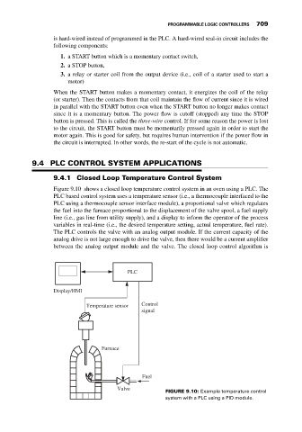
Figure 9.10 shows a closed loop temperature control system in an oven using a PLC. The
PLC based control system uses a temperature sensor (i.e., a thermocouple interfaced to the
PLC using a thermocouple sensor interface module), a proportional valve which regulates
the fuel into the furnace proportional to the displacement of the valve spool, a fuel supply
line (i.e., gas line from utility supply), and a display to inform the operator of the process
variables in real-time (i.e., the desired temperature setting, actual temperature, fuel rate).
The PLC controls the valve with an analog output module. If the current capacity of the
analog drive is not large enough to drive the valve, then there would be a current amplifier
between the analog output module and the valve. The closed loop control algorithm is
PLC
Display/HMI
Temperature sensor Control
signal
Furnace
Fuel
Valve
FIGURE 9.10: Example temperature control
system with a PLC using a PID module.