
Page 724 - Mechatronics with Experiments
P. 724
710 MECHATRONICS
implemented in the ladder logic diagram using a PID algorithm function block where the
parameters of the algorithm are to be tuned by the application engineer. The PID control
algorithm determines the command signal to the valve (how much it should open) based on
the desired temperature (which may be programmed by the operator using the HMI device
interface) and the actual temperature measurement from the temperature sensor. The PID
algorithm can be implemented either in the ladder logic diagram in software or the PID
implementation can be handled by a dedicated PID I/O module. A PID I/O module would
be placed in the rack of the PLC, and has one analog input connected to the temperature
sensor, and one analog output connected to the valve, and the desired temperature is a data
that is defined by the ladder logic using the HMI and passed to the PID module via the
backplane communication bus.
9.4.2 Conveyor Speed Control System
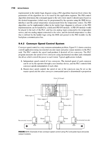
Conveyor speed control is a very common automation problem. Figure 9.11 shows a motion
control application using incremental encoder input and pulse output modules in the PLC
rack. The PLC controls the speed (and position if desired) of two conveyors. The PLC
program measures the speed of two conveyors using incremental encoders and commands
the drives which control the power to each motor. Typical applications include:
1. Independent speed control of two conveyors. The desired speed of each conveyor
can be set by the operator through a user interface device, and the PLC controls both
conveyor speeds independent of each other.
2. Master-slave speed control: the speed of one of the conveyors may be set as the
master speed and the other conveyor commanded speed is determined in proportion
Pulse I/O board
Pulse input 1
Pulse input 2
Pulse output 2 Pulse output 1
Motor drive Motor drive
Motor Motor
Incremental encoder Incremental encoder
FIGURE 9.11: Example of two conveyor speed control using PLC and pulse input and pulse
output modules.