
Page 756 - Mechatronics with Experiments
P. 756
742 MECHATRONICS
PE PE - E PE - L PE - H
V V V
1 2 3
Input conveyor (#1) Smart conveyor (#2) Output conveyor (#3)
l p l 1
l 3
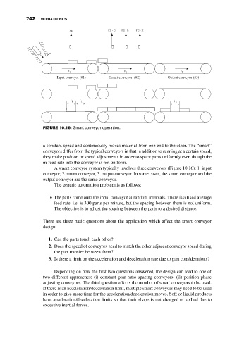
FIGURE 10.16: Smart conveyor operation.
a constant speed and continuously moves material from one end to the other. The “smart”
conveyors differ from the typical conveyors in that in addition to running at a certain speed,
they make position or speed adjustments in order to space parts uniformly even though the
in-feed rate into the conveyor is not uniform.
A smart conveyor system typically involves three conveyors (Figure 10.16): 1. input
conveyor, 2. smart conveyor, 3. output conveyor. In some cases, the smart conveyor and the
output conveyor are the same conveyor.
The generic automation problem is as follows:
The parts come onto the input conveyor at random intervals. There is a fixed average
feed rate, i.e. is 300 parts per minute, but the spacing between them is not uniform.
The objective is to adjust the spacing between the parts to a desired distance.
There are three basic questions about the application which affect the smart conveyor
design:
1. Can the parts touch each other?
2. Does the speed of conveyors need to match the other adjacent conveyor speed during
the part transfer between them?
3. Is there a limit on the acceleration and deceleration rate due to part considerations?
Depending on how the first two questions answered, the design can lead to one of
two different approaches: (i) constant gear ratio spacing conveyors; (ii) position phase
adjusting conveyors. The third question affects the number of smart conveyors to be used.
If there is an acceleration/deceleration limit, multiple smart conveyors may need to be used
in order to give more time for the acceleration/deceleration moves. Soft or liquid products
have acceleration/deceleration limits so that their shape is not changed or spilled due to
excessive inertial forces.