
Page 848 - Mechatronics with Experiments
P. 848
834 MECHATRONICS
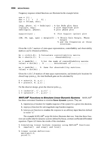
Frequency response related functions are illustrated in the example below.
num = [1] ;
den = [1 5 2 6];
sys = tf(num, den);
[mag, phase, w] = bode(sys) ; % Get Bode plot data
loglog(w, mag); % plot magnitude plot
semilogx(w, phase); % plot phase plot
nyquist(sys) ; % Plot Nyquist (polar) plot
[GM, PM, wgm, wpm] = margin(G) ; % Obtain Gain Margin, Phase
margin
% and the freqencies at those
locations.
Given the A, B, C matrices of state-space representation, controllability and observability
matrices can be obtained as follows,
Wc = ctrb(A,B); % Calcualate controllability matrix
Wo = obsv(A,C); % ........... observability........
nc = rank(Wc) ; % Get the rank of controllability matrix
value1 = det(Wc) ; % ....... determinant of ..............
no = rank(Wo) ; % Same for observability matrices.
value2 = det(Wo) ;
Given the A, B, C, D matrices of state-space representation, and desired pole locations for
closed loop system p , the state feedback gain can be calculated by
c
K = acker(A, B, p_c) ;
K = place(A, B, p_c) ;
For the observer design, given the observer poles, p ,
e
L = (acker(A’, C’, p_e))’ ;
L = (place(A’, C’, p_e))’ ;
®
MATLAB Functions to Simulate Linear Dynamic Systems MATLAB ®
has three convenient functions to simulate linear dynamic systems. They are
1. impulse(sys,t) function for impulse response of the system for a given time duration,
2. step(sys,t) function for unit magnitude step function response,
3. lsim(sys,u,t) function to simulate the response to an arbitrary input function defined
in vector “u.”
®
The example MATLAB script file below illustrates their use. Note that these func-
tions are usable only for dynamic systems defined by linear, constant coefficient differential
equations. Figure A.9 shows the results of the simulation.
% Simulating Linear Systems response using MATLAB® Functions
% impulse() and step() and lsim()
% Linear system definition:
wn=2∗pi∗1.0;
psi=0.5;