Page 889 - Mechatronics with Experiments
P. 889

®
                                                               ®
                                                MATLAB , SIMULINK , STATEFLOW, AND AUTO-CODE GENERATION  875
                                           hd
                                                   mode
                                           h
                                Scope 1
                                            Supervisory controller       Scope 2
                                                                                                1
                                                                        Ka   Kv       +   1/A
                                       +                                                        s
                                            Mode 1: Relay with         Amplifier Valve gain:  Valve  –  Area  Integrator
                                       –      hysteresis   DAC: Quantizer  DAC: ZOH
                               Desired liquid          Multiport  10-bit   Flow rate/current  Add
                                level  Add 1           switch logic
                                               K2
                                                                                           1/R
                                             Mode 2: Gain
                                                          Model info: This model simulates a liquid level control problem.  Resistance gain
                                                          Simulink models a three different controllers,
                                                          A supervisory controllers modeled in stateflow selects
                                               K3         which mode (one of three) the controller should operate.
                                             Mode 3: Gain 1
                                                                                1
                                                               ADC: Quantizer  Sensor: Liquid level
                                                                  10-bit
                             FIGURE A.45: Liquid level control example using a Stateflow chart for supervisory control
                             logic.
                                  if (err < err_th1)     %  Supervisory control logic: select
                                                            controller mode.
                                     control_mode = 1;
                                  elseif (err >= err_th1 and err < err_th2 )
                                     control_mode = 2;
                                  elseif (err >= err_th2)
                                     control_mode = 3;
                                  end

                                                                        ®
                                  Figures A.45 and A.46 show the new Simulink block diagram of the liquid level
                             control system as well as the Stateflow chart for this very simple supervisory controller.
                             A simulation result is shown in Figure A.47. The simulation was run for the following


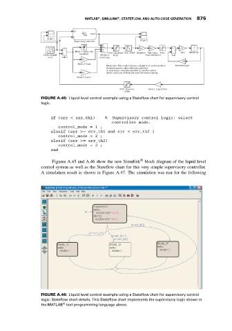
                             FIGURE A.46: Liquid level control example using a Stateflow chart for supervisory control
                             logic: Stateflow chart details. This Stateflow chart implements the supervisory logic shown in
                                       ®
                             the MATLAB text programming language above.
   884   885   886   887   888   889   890   891   892   893   894