
Page 886 - Mechatronics with Experiments
P. 886
872 MECHATRONICS
For convenience, we copied all the files for illustration purposes here in the figure. Note
®
that this is a “MATLAB Function” of an embedded kind. Only the data visible to it are
passed in its argument list. The “ml” operator we used in the Stateflow graphical model
®
file is not available to access MATLAB workspace data. If we need to access MATLAB ®
workspace data which are not passed by the function call arguments, then we must use the
“global” declaration. For instance, in the function “StateX_Action(u),” we define the Kp
®
as a local variable. The Kp of the MATLAB workspace can not be accessed via “ml.Kp.”
®
If it is desired to access the Kp of the MATLAB workspace instead of using a local Kp,
then the “global” declaration must be used.
Example: Use of C-Functions in Stateflow Chart The purpose of this exam-
ple is to illustrate how to incorporate C-functions into Stateflow charts. Simply follow the
order of activities in the dialog windows as shown in Figures A.43 and A.44. There are four
C-functions which are called from the Stateflow chart;
StateX_Action(u) ;
TransitionY2X_Action() ;
StateY_Action(u);
TransitionX2Y_Action() ;
The source code for these four C-functions is in the file named
StateFlow_C_Function_Example.c
The declarations (include statements) code for each function is typed directly into the
dialog box.
Example: Liquid Level in a Tank Control Problem with Multiple Modes
of Controller Operation For the purpose of illustrating how a typical Stateflow
®
chart can be used as part of a Simulink model, let us assume that the controller logic is now
®
different than the one implemented in the Simulink example. The new controller we want
to implement here has three modes of operation. In each mode, a different control algorithm
is implemented with different parameters. A supervisory control logic is to monitor the
sensor signal for the measured liquid height and the desired height data, then decide on
an output value that selects one of three modes of operation. Using that information, the
®
Simulink part of the code is to execute the selected control algorithm.
®
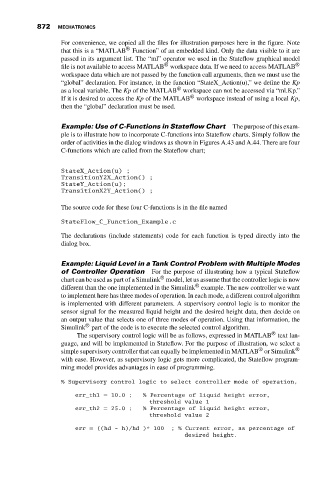
The supervisory control logic will be as follows, expressed in MATLAB text lan-
guage, and will be implemented in Stateflow. For the purpose of illustration, we select a
®
simple supervisory controller that can equally be implemented in MATLAB or Simulink ®
with ease. However, as supervisory logic gets more complicated, the Stateflow program-
ming model provides advantages in ease of programming.
% Supervisory control logic to select controller mode of operation,
err_th1 = 10.0 ; % Percentage of liquid height error,
threshold value 1
err_th2 = 25.0 ; % Percentage of liquid height error,
threshold value 2
err = ((hd - h)/hd )* 100 ; % Current error, as percentage of
desired height.