
Page 101 - Servo Motors and Industrial Control Theory -
P. 101
94 5 Stepping Servo Motors
+∇
’r r
A C B D
OSCILLATOR AND TRANSLATOR
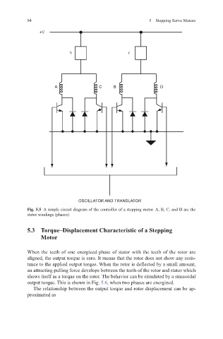
Fig. 5.5 A simple circuit diagram of the controller of a stepping motor. A, B, C, and D are the
stator windings (phases)
5.3 Torque–Displacement Characteristic of a Stepping
Motor
When the teeth of one energized phase of stator with the teeth of the rotor are
aligned, the output torque is zero. It means that the rotor does not show any resis-
tance to the applied output torque. When the rotor is deflected by a small amount,
an attracting pulling force develops between the teeth of the rotor and stator which
shows itself as a torque on the rotor. The behavior can be simulated by a sinusoidal
output torque. This is shown in Fig. 5.6, when two phases are energized.
The relationship between the output torque and rotor displacement can be ap-
proximated as