
Page 100 - Servo Motors and Industrial Control Theory -
P. 100
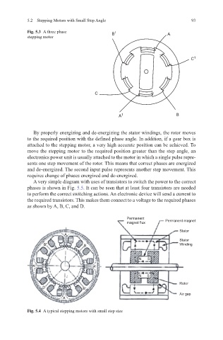
5.2   Stepping Motors with Small Step Angle                     93


            Fig. 5.3   A three phase         B 1
            stepping motor                                         A


                                                                            C 1


                                      C


                                                A 1                   B


              By properly energizing and de-energizing the stator windings, the rotor moves
            to the required position with the defined phase angle. In addition, if a gear box is
            attached to the stepping motor, a very high accurate position can be achieved. To
            move the stepping motor to the required position greater than the step angle, an
            electronics power unit is usually attached to the motor in which a single pulse repre-
            sents one step movement of the rotor. This means that correct phases are energized
            and de-energized. The second input pulse represents another step movement. This
            requires change of phases energized and de-energized.
              A very simple diagram with uses of transistors to switch the power to the correct
            phases is shown in Fig. 5.5. It can be seen that at least four transistors are needed
            to perform the correct switching actions. An electronic device will send a current to
            the required transistors. This makes them connect to a voltage to the required phases
            as shown by A, B, C, and D.

                                                   Permanent
                                                   magnet flux    Permanent magnet
                                                                        Stator
                          A
                                                                        Stator
                  B'              B                                     Winding


                                                        N  S
              A'                      A'

                                                        N  S
                                                                        Rotor
                  D               B'
                                                                        Air gap
                          A

            Fig. 5.4   A typical stepping motors with small step size