
Page 95 - Servo Motors and Industrial Control Theory -
P. 95
88 4 Electrical DC Servo Motors
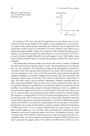
Fig. 4.17 Voltage character- Output Voltage
istic of PWM system against
mark-space ratio %100
%50
0
0 0.5 1
Mark space ratio
In selecting a DC motor for specific application several factors must be con-
sidered. The DC motor studied in this chapter was an example how to use numeri-
cal values in the system model. Sometimes the inductance can be ignored but for
closed loop control it must be considered. The motor studied in this chapter was a
permanent magnet and the voltage was connected to the armature through a pair of
brushes. The permanent magnet has great influence on the performance of DC mo-
tor and it becomes smaller when the rare earth magnet is used. The brushes cause
some reliability problem and to overcome this problem brushless DC motor can be
designed.
The information one must obtain is the torque and velocity constant, in addition
the rated and maximum starting torque are some important parameters even though
they are not considered. The maximum starting torque determines the initial ac-
celeration of the rotor and any inertia attached to the motor. The electronics circuit
must be designed in such a way to limit the maximum current passes through the
armature windings to avoid the windings from burning. This also determines the
maximum output torque of the motor which must be operated for a short period of
time. The rated torque can be operated continuously without worrying about the
above mentioned problem. There are three types of drive unit for DC motor. One is
a single phase thyristor controlled drive unit which is relatively cheap to buy but the
problem of speed fluctuation should be tolerated. This type of drive is suitable for
low performance applications and it can be used both for position and velocity con-
trol. It cannot produce great position/velocity stiffness against the external torque.
The frequency of output pulses is 50 Hz for bidirectional application or 100 Hz for
one direction only. The second type of drive unit is three phase Thyristor controlled
system which can produce output pulse frequency of 150 Hz for bidirectional appli-
cations and 300 Hz for one direction rotating speed. The second type is much better
than the first one because the fluctuation of speed is greatly reduced. The third type
is PWM type which is more expensive than the first two types because the three
phase power supply has to be rectified. After rectification for small motor power
transistors can be used to generate square wave form. The frequency of pulse could
be greater than 2 kHz which is sufficiently great to reduce the speed fluctuation to a
negligible value. For motor with power greater that a fraction of KW Thyristors are
used to generate the square pulses. The problem with Thyristors is that once they