
Page 94 - Servo Motors and Industrial Control Theory -
P. 94
4.8 Effect of Form Factor on Speed Fluctuation 87
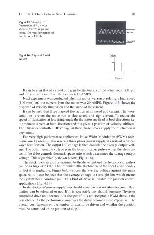
Fig. 4.15 Velocity of
fluctuation of the motor
at current of 20 amps and
speed 100 rpm. Frequency of 4 RPM
oscillation = 150 Hz
20 AMPS
Fig. 4.16 A typical PWM Mark
system
Space
It can be seen that at a speed of 6 rpm the fluctuation of the actual rotor is 8 rpm
and the current drawn from the system is 20 AMPS.
Next experiment was conducted when the motor was run at relatively high speed
(100 rpm) and the current from the motor was 20 AMPS. Figure 4.15 shows the
response of velocity fluctuation and the shape of the current.
It can be seen that three is speed fluctuation at all speed and current. The worst
condition is when the motor run at slow speed and high current. To reduce the
speed of fluctuation at low firing angle the thyristors are fired at both directions i.e.
it produces current at both direction and this gives a position or velocity stiffness.
The Thyristor controlled DC voltage at three phase power supply the fluctuation is
very small.
For very high performance application Pulse Width Modulation (PWM) tech-
nique can be used. In this case the three phase power supply is rectified with full
wave rectification. The output DC voltage is then controls the average output volt-
age. The output variable voltage is in the form of square pulses where the electron-
ics in the drive controls the mark space ratio which determines the average output
voltage. This is graphically shown below, (Fig. 4.16).
The mark space ratio is determined by the drive unit and the frequency of pulses
can be as high as 2 kHz. This minimizes the fluctuation of the speed considerably
in fact it is negligible. Figure below shows the average voltage against the mark
space ratio. It can be seen that the average voltage is a straight line which means
the system has a constant gain. This kind of drive is suitable for position control
applications (Fig. 4.17).
In the design of power supply one should consider that whether the small fluc-
tuation can be tolerated or not. If it is acceptable one should purchase Thyristor
controlled drive unit because it is cheaper. If it is not acceptable PWM drive is the
best choice. As the performance improves the drive becomes more expensive. The
overall cost depends on the number of axes to be driven and whether the position
must be controlled or the position of output.