
Page 93 - Servo Motors and Industrial Control Theory -
P. 93
86 4 Electrical DC Servo Motors
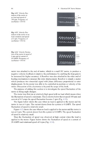
Fig. 4.12 Velocity fluc-
tuation of the motor at 1
no load and speed of RPM
100 rpm. Frequency of
oscillation = 150 Hz
4.5
AMS
Fig. 4.13 Velocity fluc-
tuation of the motor at no
load condition and speed
of 6 rpm. Frequency of 2 RPM
oscillation = 150 Hz
4 AMPS
Fig. 4.14 Velocity fluctua-
tion of the motor at speed of
6 rpm and at current of 8 RPM
20 AMPS. Frequency of
oscillation = 150 Hz
20 AMPS
meter was attached to the end of motor, which is a small DC motor, to produce a
negative velocity feedback to improve the performance by enabling the loop gain to
be increased for higher accuracy. A Resolver was also attached to the other end of
loading mechanism to measure the rotor displacement. Resolver is simply a motor
which produces two sinusoidal signal with phase difference proportional to rotor
displacement. So the motor was able to be controlled in position or velocity of the
motor. Discussion of the electronics is beyond the scope of the book.
The purpose of adding this section is to investigate the speed fluctuation of the
motor as firing angle changes.
The motor was first run at relatively high speed with no load which means when
the fluctuation of speed is minimum. This is shown below that at speed 100 rpm and
current of 4.5 amps the speed fluctuation become 1 rpm (Fig. 4.12).
The figure below shows the case when no load is applied to the motor and the
motor is run at 6 rpm. The current drawn from the system is 4 AMPS. The speed
fluctuation of speed is relatively small.
Figure 4.13 shows the case when no load is applied to the motor and the motor is
run at 6 rpm. The current drawn from the system is 4 AMPS. The speed fluctuation
of speed is relatively small.
Then the fluctuation of speed was observed at high current when the load is
applied to the motor. Figure below shows the fluctuation of speed at a current of
20 AMPS and rotational speed of 6 rpm (Fig. 4.14).