
Page 102 - Servo Motors and Industrial Control Theory -
P. 102
5.3 Torque–Displacement Characteristic of a Stepping Motor 95
torque due to phase
Resultant torque
cw
torque
Torque due to phase 2
ccw rotor cw rotor
displacement displacement
ccw ¼ rotor ¼ rotor
torque tooth tooth
pitch pitch
180 90 0 90 180
Rotor position, θ, deg.
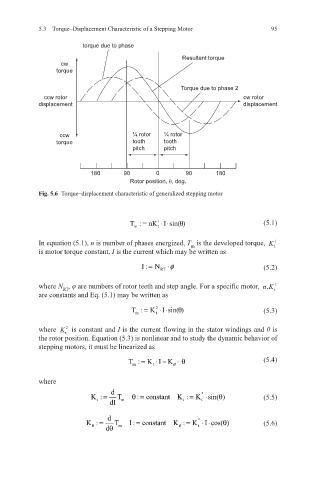
Fig. 5.6 Torque–displacement characteristic of generalized stepping motor
T: =nKI sin( )⋅⋅ θ (5.1)
1
m t
In equation (5.1), n is number of phases energized, T is the developed torque, K
1
m
t
is motor torque constant, I is the current which may be written as
I: = N RT φ ⋅ (5.2)
where N , φ are numbers of rotor teeth and step angle. For a specific motor, nK, 1 t
RT
are constants and Eq. (5.1) may be written as
T : = K I sin()⋅ ⋅ θ (5.3)
2
m t
where K is constant and I is the current flowing in the stator windings and θ is
2
t
the rotor position. Equation (5.3) is nonlinear and to study the dynamic behavior of
stepping motors, it must be linearized as
T: = K I K ⋅ − θ ⋅θ (5.4)
m
t
where
K : = d T θ= K : = K sin( )⋅ θ (5.5)
2
: constant
t
dI m t t
d
K : = dθ T m I : constant K : = K ⋅⋅ (5.6)
2
=
I cos( ) θ
θ
θ
t