
Page 144 - Servo Motors and Industrial Control Theory -
P. 144
8.4 Properties of ER Fluid in Shear Mode 139
10
+ 500 t per
9 ++ 1000 t per
1500 t per
2000 t per
8 * 2500 t per
7
Current (mAmp) 6 5 4
3 +
+
2
+
1 +
+
0
0 200 400 600 800 1000 1200 1400 1600 1800 2000
Voltage (v)
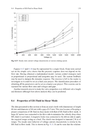
Fig. 8.15 Steady state current-voltage characteristic at various rotating speeds
Figures 8.13 and 8.14 may be represented by a single block. From tests carried
out on the simple valve shows that the pressure response does not depend on the
flow rate. Having obtained a mathematical model, various control strategies such
as proportional or proportional and integrator may be used. The current feedback
may be used to dampen the dynamic response. The exercise is left to the reader to
investigate or it could be set as a final year project. The identification procedure of
obtaining all the parameters can be set as a master year project. This exercise can be
repeated for various flow rates and voltages and gaps.
Another research area is to study the valve properties over different valve length
and diameter although from above analysis they can be predicted.
8.4 Properties of ER Fluid in Shear Mode
The data presented in this section is from an axial clutch with dimensions of length
60 mm and diameter of 60 mm with a gap of 0.5 mm. This was because of keeping a
proper comparison of ER fluid in shear mode with that of ER fluid in flow mode. A
large AC motor was connected to the drive side to minimize the velocity drop when
ER clutch is activated. A magnetic brake was connected to the driven side to apply
the required torque acting as a load. The clutch was designed to transmit 2 N m of
torque. The steady state behavior of voltage current characteristic is similar to the
ER fluid in flow mode. This is shown in Fig. 8.15. It can be seen that the relation-