Page 443 - Icon Ridge Presents ATORN
P. 443
Turning tools \ Technical introduction – CBN turning

                       Cutting edge design for CBN cutting materials


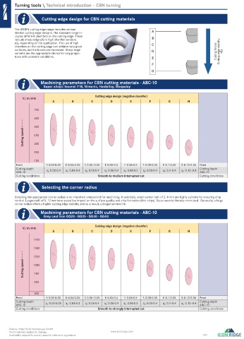
        The ATORN cutting edge range includes various
        distinct cutting edge designs. The standard range in-           A
        cludes diff erent chamfers on the cutting edge. These
        include sharp-edge (A) to high chamfer versions                 B
        (G), depending on the application. The use of high
        chamfers on the cutting edge can achieve very good              C
        surfaces, but the forces are increased. Sharp-edge              D
        variants are the appropriate choice for long projec-                                           Cutting forces  Cutting edge stability  <Rz
        tions with unstable conditions.                                 E
                                                                        F
                                                                        G

                      Machining parameters for CBN cutting materials - ABC-10
                       Super alloys: Inconel 718, Nimonic, Hastelloy, Waspaloy

                                              Cutting edge design (negative chamfer)
            V c: m/min
                          A        B        C        D        E        F        G        H

                 700
                 600
            Cutting speed → → →  500  V c  V c  V c  V c      V c      V


                 400
                                                                        c
                                                                                V
                                                                                 c
                 300
                                                                                         V c
                 200
                 100
         Feed          f: 0.02-0.25  f: 0.04-0.25  f: 0.05–0.25  f: 0.05-0.4  f: 0.06-0.5  f: 0.08-0.35  f: 0.1-0.35  f: 0.12-0.35  Feed
         Cutting depth   a p: 0.02-0.4  a p: 0.03-0.4  a p: 0.06-0.4  a p: 0.06-0.4  a p: 0.08-0.5  a p: 0.08-0.4  a p: 0.1–0.4  a p: 0.12–0.4  Cutting depth
         ABC-10                                                                                ABC-10
         Cutting conditions                    Smooth to medium interrupted cut                Cutting conditions

                      Selecting the corner radius

          Selecting the appropriate corner radius is an important component for machining: In principle, small corner radii of 2, 4 mm are highly suitable for ensuring chip
        control. Larger radii of 8, 12 mm have a positive impact on the surface quality and chip formation (thin chips). Scour wear is thereby minimized.  Generally, a large
        corner radius off ers a higher cutting edge stability and as a result, a longer service life.
                      Machining parameters for CBN cutting materials - ABC-10
                       Grey cast iron GG20 - GG25 - GG30 - GG40

                                              Cutting edge design (negative chamfer)
            V c: m/min
                          A        B        C        D        E        F        G        H

                 1750
                 1500    V c       V
            Cutting speed → → →  1000  c    V c      V c      V c      V c      V c
                 1250


                 750

                 500                                                                     V c

                 300
         Feed          f: 0.02-0.25  f: 0.04-0.25  f: 0.05–0.25  f: 0.05-0.4  f: 0.06-0.5  f: 0.08-0.35  f: 0.1-0.35  f: 0.12-0.35  Feed
         Cutting depth   a p: 0.02-0.25  a p: 0.03-0.3  a p: 0.06-0.4  a p: 0.06-0.4  a p: 0.08-0.5  a p: 0.08-0.4  a p: 0.1–0.4  a p: 0.12–0.4  Cutting depth
         ABC-10                                                                                ABC-10
         Cutting conditions                    Smooth to strongly interrupted cut              Cutting conditions


     Source: Hahn+Kolb Werkzeuge GmbH
     Technical data subject to change.               www.iconridge.com
     Availability subject to country specific rules and regulations.                            443

   0576_EN_2018_KERN[21847876]-l.indd  576                                                            12/17/2018  3:33:08 PM

