Page 475 - Icon Ridge Presents ATORN
P. 475
Turning tools \ ISO clamp holders for internal machining

                     Overview of ISO boring bars


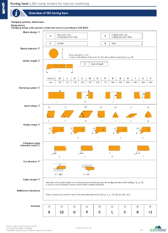
         Clamping systems, dimensions
         Designations
         Clamping holder with cylindric shank (boring bar) according to DIN 8024
                 Shank design ➀
                                   A    Steel with inner                E    Carbide with inner
                                        cooling lubrication feed
                                                                             cooling lubrication feed
                                   C    Carbide                         S    Steel
               Shank diameter ➁

                                                Shank diameter in mm.
                                                In case of diameters of less than 10 mm, there will be a leading 0, e. g. 08.
                 Holder length ➂
                                                          X    Special length


                                 Symbols  H    J    K    L    M    N    P    Q     R    S    T    U    V
                                   mm   100   110  125  140  150  160  170   180  200  250  300  350   400

              Clamping system ➃


                 Insert shape ➄
                                                          55°


                                                           K
                 Holder shape ➅


                 Clearance angle
               indexable insert ➆


                 Cut direction ➇


                                       R = right          L = left
                 Cutter length ➈
                                Indication of the cutter length in mm without decimal point, in case of one-digit numerals with leading 0 (e. g. 08).
                                In case of round indexable inserts, the diameter is always indicated.
             Additional indications
                                These indications do not form part of the standard and are facultative, e. g. "-U" stands: with shim.


                      Example     ➀       ➁        ➂        ➃       ➄        ➅       ➆        ➇        ➈
                                  S       32       U        P       C        L       C        R       12


     Source: Hahn+Kolb Werkzeuge GmbH
     Technical data subject to change.               www.iconridge.com
     Availability subject to country specific rules and regulations.                            475

   0607_EN_2018_KERN[21847920]-l.indd  608                                                            12/17/2018  3:33:35 PM

