
Page 286 - Industrial Tools Catalog (2)
P. 286
Layer thickness/wall thickness/corrosion protection measuring instruments \ Ultrasonic wall thickness gauges
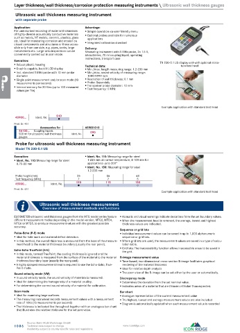
Ultrasonic wall thickness measuring instrument
with separate probe
Application: Advantage:
For undisturbed recording of material thicknesses Simple operation via user-friendly menu
of highly-diverse acoustically conductive materials Optional probes available for numerous
such as metals, NF metals, ceramic, plastics, glass applications
etc. Ideal for monitoring corrosion and erosion on Integrated calibration standard
closed components and structures or those acces-
sible only from one side, e.g. pipes, tanks, large Delivery:
metal sheets etc. Large-area inspections can be Measuring instrument with 5 MHz probe, 2x 1.5 V,
conveniently carried out in scan mode. AA batteries, 70 ml coupling liquid, operating
Execution: instructions, transport case TN 230-0.1 US display unit with optional minia-
Robust plastic housing Technical data: ture test head
Graphic-capable, backlit LCD display Min./max. length measuring range: 1.2-230 mm
Incl. standard 5 MHz probe with 10 mm probe Min./max. sound velocity of measuring range:
diameter 1000-9999 m/s
Single point measurement and/or scan mode (10 Resolution of wall thickness: 0.1 mm
measurements per second) Probe: Separately
Internal memory for 20 files (up to 100 measured Transceiver probe diameter: 10 mm
Test frequency: 5 MHz
values per file)
Example application with standard test head
45900... Ident. No. 010
●
Prod. Gr. 451
Accessories for 45900 010
46100... Coupling liquids 090
500 ml for ultrasonic wall thickness Ident. No. ●
gauges
Probe for ultrasonic wall thickness measuring instrument
Model TN 230-0.1 US
Execution: Ident. No. 115: Measuring range for steel
Ident. No. 110: Measuring range for steel 1-225 mm at normal temperature, 4-100 mm for
0.75-80 mm applications up to 300°
Ident. No. 150: Measuring range for steel
1.2-230 mm
Probe height (mm) 25 86 68
Test frequency (MHz) 7 7 5
45900... Ident. No. 110 115 150
●
○
○
Prod. Gr. 451
Example application with standard test head
Ultrasonic wall thickness measurement
Overview of measurement methods and functions
ELCOMETER ultrasonic wall thickness gauges from the MTG model series feature Acoustic and visual warnings indicate deviations from the set boundary values.
different measurement modes depending on the model version, MTG2, MTD4, When the measurement head is removed, the average, lowest and highest
MTG6 or MTG8, to produce measurement values with the greatest possible thickness values are indicated.
accuracy.
Sequence or grid lots
Pulse-Echo (P-E) mode Individual measurement values can be saved in up to 1,000 alphanumeric
Ideal for hole mark and material defect detection. sequence or grid lots.
In this method, the overall thickness is measured from the base of the measure- Where grid lots are used, the measurement values are saved in a type of calcu-
ment head to the material thickness boundary (usually the rear panel). lation table.
Echo-Echo TruePaint (E-E) Grid lots: The inaccessibility function allows inaccessible areas to be saved in
the grid.
In this mode, termed TruePaint, the coating thickness is ignored and the
material thickness is measured from the surface of the material to the material B-image measurement value
thickness boundary layer (usually the rear panel). Time-based, two-dimensional cross-section B-image facilitates graphical
A highly damped measurement head is required to use the Echo-Echo, True- rendering of the material thickness
Paint mode. Ideal for relative depth analysis
Sound velocity mode (VM) The zoom view of the B-image can be set either by the user or automatically.
In sound velocity mode, the sound velocity of materials is measured. Discrepancy mode
Ideal for determining the homogeneity of a material or alloy. Determines the deviation from the set nominal value.
For determining the correct sound velocity of a material for calibration. Indicates areas of a material that are thinner or thicker than expected.
Scan mode Bar chart
Ideal for examining large surfaces. Analogue representation of the current measurement value
The measuring instrument records measurement values with a measurement The highest, lowest and average measurement values are also included
rate of 16Hz (16 measurements per second) Diagram is automatically updated when each measurement value is recorded
The thickness is indicated live throughout together with an analogous bar chart
that illustrates the relative thickness for the set zero value.
Source: Hahn+Kolb Werkzeuge GmbH
1086 Technical data subject to change. www.iconridge.com
Availability subject to country specific rules and regulations.