
Page 208 - GM E-BOOKLET 2022
P. 208
To facilitate the energization of the coil of the Feeder
Contactors; when the supply is taken from the output side,
Rotary Switches (BSW-1 & BSW-4) are provided in respective
Feeder Contactors 1 & 2 circuit.
b) The HOG Contactors cannot be CLOSED as the coils cannot be
energized from the supply available output side of the HOG
Contactors - A & B.
To facilitate the energization of the coil of the HOG Contactors;
when the supply is taken from the output side, Rotary Switches
(BSW-2 & 3, BSW-5 & 6) are provided in respective HOG
Contactors - A & B circuit.
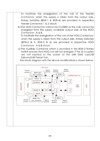
c) The Auxiliary Contactor which is provided in the BSW-3 Rotary
Switch ensures that HOG coil will not energize; if the ZS couplers
are not inserted to the socket of the LHB OMS car/LHB
Saloons/LHB Parcel Van.
The block diagram with the above modifications is shown below:
206