
Page 13 - Basic PD Theory
P. 13
Partial Discharge for Stator Windings
where this surface voltage abruptly goes from close to full
voltage to zero (semi-conductive) and makes it hard for the
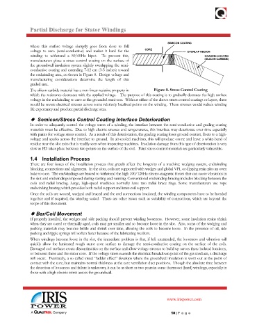
winding to withstand a 50/60Hz hipot. To prevent this,
manufacturers place a stress control coating on the surface of
the groundwall insulation system slightly overlapping the semi-
conductive coating and extending 7-12 cm (3-5 inches) toward
the endwinding area, as shown in Figure 8. Design voltage and
manufacturing considerations determine the length of this
graded area.
The silicon carbide material has a non-linear resistive property in Figure 8. Stress Control Coating
which the resistance decreases with the applied voltage. The purpose of this coating is to gradually decrease the high surface
voltage in the endwinding to zero at the grounded semi-con. Without either of the above stress control coatings or layers, there
would be severe electrical stresses across some relatively localized points on the winding. These stresses would reduce winding
life expectancy and produce partial discharge sites.
Semicon/Stress Control Coating Interface Deterioration
In order to adequately control the voltage stress of a winding, the interface between the semi-conductive and grading coating
materials must be effective. Due to high electric stresses and temperatures, this interface may deteriorate over time especially
with paints for voltage stress control. As a result of this deterioration, the grading coating loses ground contact, floats to a high-
voltage and sparks across the interface to ground. In air-cooled machines, this will produce ozone and leave a white-band of
residue near the slot exits that is readily seen when inspecting machines. Insulation damage from this type of deterioration is very
slow as PD takes place between two points on the surface of the coil. Paint stress control materials are particularly vulnerable.
1.4 Installation Process
There are four issues of the installation process that greatly affect the longevity of a machine: wedging system, endwinding
blocking, connections and alignment. In the slots, coils are supported with wedges and global VPI, or dipping resin plus an oven
bake to cure. The endwindings are braced to withstand the high 100/120Hz electro-magnetic forces that can cause vibrations in
the slot and endwindings imposed during starting and running. Conventional endwinding bracing includes blocking between the
coils and radial bracing. Large, high-speed machines normally have two radial brace rings. Some manufacturers use rope
endwinding bracing which provides both radial support and inter-coil support.
Once the coils are wound, wedged and braced and the end connections insulated, the winding components have to be bonded
together and if required, the winding sealed. There are other issues such as suitability of connections, which are beyond the
scope of this document.
Bar/Coil Movement
If properly installed, the wedges and side packing should prevent winding looseness. However, some insulation resins shrink
when they are cured or thermally aged, coils may get smaller and so become loose in the slot. Also, some of the wedging and
packing materials may become brittle and shrink over time, allowing the coils to become loose. In the presence of oil, side
packing and ripple springs will soften faster because of the lubricating medium.
When windings become loose in the slot, the immediate problem is that, if left unattended, the looseness and vibration will
quickly allow the laminated rough stator core surface to damage the semi-conductive coating on the surface of the coils.
Damaged coil surfaces create discontinuities on the surface and allow voltage stresses to build up across these isolated locations,
or between these and the stator core. If the voltage stress exceeds the electrical breakdown point of the gas medium, a discharge
will occur. Eventually, a so called visual “ladder effect” develops where the groundwall insulation is worn out at the point of
contact with the core, but maintains normal thickness at the core ventilation duct positions. Though the absolute time between
the detection of looseness and failure is unknown, it can be as short as two years in some thermoset (hard) windings, especially in
those with a high electric stress across the groundwall.
www.irispower.com
10 | P ag e