
Page 8 - Basic PD Theory
P. 8
Partial Discharge for Stator Windings
1.1.1.2 Multi-turn Coils
A multi-turn coil, Figure 4, is formed by taking a group of insulated copper
strands to form the turn cross-section required and wrapping, if specified, several
layers of turn insulation around them. The bundle is then wrapped with the
specified number of turns around a jig and eventually pulled and formed into the
final familiar “diamond” shape. The entire coil is then insulated with multiple
layers of groundwall tape.
A concentric coil is formed by taking a group insulated copper strands to form the
conductor cross-section required and taping, if specified, several layers of turn
insulation around them. These are then bundled together before being formed
into a “u” shape. Then, except for the outer ends, the “u” shaped coil is insulated
with multiple layers of groundwall tape. Since the winding formed by these coils is
Figure 4: Diamond Coil concentric, different sizes of coil are required. The core for this type of winding
has semi-enclosed slots and so “u” shaped coils are inserted from one end and
then connected at the other end to form a concentric, multi-turn coil.
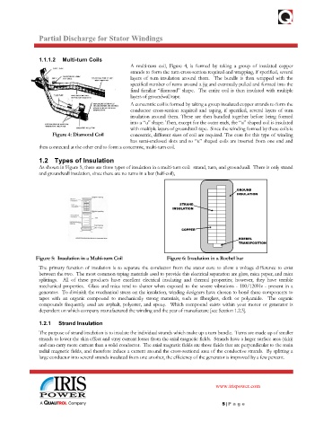
1.2 Types of Insulation
As shown in Figure 5, there are three types of insulation in a multi-turn coil: strand, turn, and groundwall. There is only strand
and groundwall insulation, since there are no turns in a bar (half-coil),
GROUND
INSULATION
STRAND
INSULATION
COPPER
ROEBEL
TRANSPOSITION
Figure 5: Insulation in a Multi-turn Coil Figure 6: Insulation in a Roebel bar
The primary function of insulation is to separate the conductor from the stator core to allow a voltage difference to exist
between the two. The most common taping materials used to provide this electrical separation are glass, mica paper, and mica
splittings. All of these products have excellent electrical insulating and thermal properties; however, they have terrible
mechanical properties. Glass and mica tend to shatter when exposed to the severe vibrations - 100/120Hz - present in a
generator. To diminish the mechanical stress on the insulation, winding designers have chosen to bond these components to
tapes with an organic compound to mechanically strong materials, such as fiberglass, cloth or polyamide. The organic
compounds frequently used are asphalt, polyester, and epoxy. Which compound exists within your motor or generator is
dependent on which company manufactured the winding and the year of manufacture [see Section 1.2.3].
1.2.1 Strand Insulation
The purpose of strand insulation is to insulate the individual strands which make up a turn bundle. Turns are made up of smaller
strands to lower the skin effect and stray current losses from the axial magnetic fields. Strands have a larger surface area (skin)
and can carry more current than a solid conductor. The axial magnetic fields are those fields that are perpendicular to the main
radial magnetic fields, and therefore induce a current around the cross-sectional area of the conductive strands. By splitting a
large conductor into several strands insulated from one another, the efficiency of the generator is improved by a few percent.
www.irispower.com
5 | Pa g e