
Page 12 - Basic PD Theory
P. 12
Partial Discharge for Stator Windings
1.3.2.1 Semi-conductive
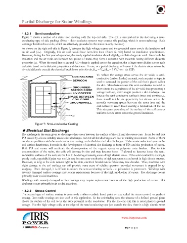
Figure 7 shows a section of a stator slot showing only the top coil side. The coil is side-packed in the slot using a semi-
conducting type of side packing. (Note - older insulation systems may contain side packing, which is non-conducting. Such
windings therefore have coils, which are effectively grounded to the stator on only one side.)
As shown on the right coil-side in Figure 7, between the high voltage copper and the grounded stator core is the insulation and
an air void (d air). Originally, this air void would have been less than .05mm (2 mils) based on installation specifications.
However, during the first year of operation, the newly applied insulation shrank slightly, and left a larger air void. Since both the
insulation and the air voids are between two pieces of metal, they form a capacitor with materials having different dielectric
properties (ε). When the rated line-to-ground AC voltage is applied across the capacitor, the voltage stress divides across each
dielectric based on its dielectric properties and thickness. An arc, or a partial discharge will occur if the electric stress across the
air-void dielectric exceeds the electrical breakdown point for air, E air = V air/d air = 3 kV/mm (at STP)
To reduce the voltage stress across the air voids, a semi-
conductive (carbon loaded) material, such as paint or tape, is
used to surround the portion of the coil that is placed within
the slot. Manufacturers use this semi-conductive material to
short-circuit the capacitance of the air void, thus preventing a
voltage build-up, which might product a slot discharge. As
long as the semi-conductive surface is intact and continuous,
there should not be an opportunity for stresses across the
naturally occurring spaces between the stator iron and the
coil surface to reach levels causing a breakdown of the air.
This adequate grounding of the surface of the coil ensures
uniform electric stress across the ground insulation.
Figure 7: Semi-conductive Coating
Electrical Slot Discharge
Slot discharge is the term given to discharges that occur between the surface of the coil and the stator core. It can be said that
PD caused by a loose winding creates slot discharges, but not all slot discharges are due to winding movement. Some of them
are due to problems with the semi-conductive coating, and called electrical slot discharges. If the semi-conductive layer on the
coil surface deteriorates, it results in the development of electrical slot discharge (a form of PD) and the production of ozone.
Both PD and ozone will accelerate the decomposition of the organic epoxy or polyester resin binders. Due to this
decomposition of the resins, the coils will decrease in size and may become loose. If allowed to become loose, the semi-
conductive surfaces of the coils are the first to be damaged causing areas of high electric stress. If the semi-conductive coating is
poorly made, especially if paint was used, it may become non-conductive at high temperatures and result in high electric stresses.
However, as long as the coils remain tight in the slots, electrical breakdown to failure may take decades. Thus, machines with
slight damage to the coil surfaces can still provide many years of reliable operation provided movement is stopped by re-
wedging. Once damaged, it is difficult to restore the semi-conducting surfaces - so prevention is paramount. Windings with
severely damaged surface coatings may require replacement because of the high production of ozone. Slot discharge occurs
primarily in air-cooled machines.
Windings with severely damaged surface coatings may require replacement because of the high production of ozone. Slot
discharge occurs primarily in air-cooled machines.
1.3.2.2 Stress Control
The second type of surface coating is commonly a silicon carbide based paint or tape called the stress control, or gradient
coating. Iron oxide coatings are also used in this application. In the endwinding area, the absence of a defined ground plane
allows the surface of the coil to be the same potential as the conductor. For the line-end coil, this is rated phase-to-ground
voltage. For the high voltage coils, at the edge of the semi-conducting tape just outside the slot, there is a high electric stress
www.irispower.com
9 | Pa g e