
Page 7 - Basic PD Theory
P. 7
Partial Discharge for Stator Windings
1.1.1 Coil Structures
There are two widely used designs of form-wound stator windings:
• a bar (half coil)
• a multi-turn coil, diamond winding
The selection of design is based on the desired power output requirements for the machine. Typically, machines rated less than
about 75MW will have multi-turn coils, while those larger than that will usually have bars. Diamond type, multi-turn coil, stator
windings can be found in machines of all vintages and are almost exclusively used in modern designs. The concentric type, multi-
turn coil, of winding can be found in some large older motors. The selection of design is based on the desired power output
requirements and power factor. The reasons for the selection are beyond the scope of this document, but generally they have to
do with manufacturability, ease of installation and repair.
1.1.1.1 Bar (half coil)
Wave-wound bars
Lap-wound bars
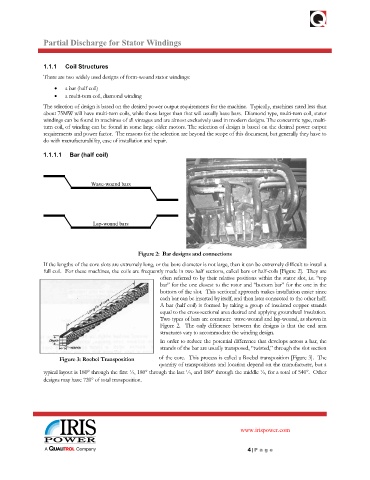
Figure 2: Bar designs and connections
If the lengths of the core slots are extremely long, or the bore diameter is not large, then it can be extremely difficult to install a
full coil. For these machines, the coils are frequently made in two half sections, called bars or half-coils [Figure 2]. They are
often referred to by their relative positions within the stator slot, i.e. “top
bar” for the one closest to the rotor and “bottom bar” for the one in the
bottom of the slot. This sectional approach makes installation easier since
each bar can be inserted by itself, and then later connected to the other half.
A bar (half coil) is formed by taking a group of insulated copper strands
equal to the cross-sectional area desired and applying groundwall insulation.
Two types of bars are common: wave-wound and lap-wound, as shown in
Figure 2. The only difference between the designs is that the end arm
structures vary to accommodate the winding design.
In order to reduce the potential difference that develops across a bar, the
strands of the bar are usually transposed, “twisted,” through the slot section
Figure 3: Roebel Transposition of the core. This process is called a Roebel transposition [Figure 3]. The
quantity of transpositions and location depend on the manufacturer, but a
typical layout is 180° through the first ¼, 180° through the last ¼, and 180° through the middle ½, for a total of 540°. Other
designs may have 720° of total transposition.
www.irispower.com
4 | Pa g e