
Page 6 - Basic PD Theory
P. 6
Partial Discharge for Stator Windings
1
Chapter
1 Stator Windings
Brief explanation of stator winding insulation systems
A
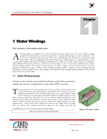
rotating machine is comprised of two major components: the stator and the rotor. The rotor develops a rotating
magnetic field and the stator is a collection of conductors, or windings, held stationary by a stator core [Figure 1]. It is
the rotor bar conductivity and shape along with the stator winding design that determine the starting and running
characteristics. The stator windings provide a path for those crazy, excitable electrons, i.e., electricity, while the stator
core focuses the magnetic field, secures the windings, and dissipates heat. Since, in a medium to high voltage stator winding the
voltage difference between the conductors and the core can be thousands of volts, it is necessary to separate the two surfaces
with an insulating material. This insulation, though necessary for isolation, support and heat transfer, serves no role in the
generation of electricity or torque. However, these insulating materials are prone to aging as a result of thermal, electrical,
environmental, and mechanical factors, and according to the Electrical Power Research Institute (EPRI) are the 2 most
nd
frequent reason for machine failure.
1.1 Stator Winding Design
Overview of the materials and construction techniques used for form-wound stator
winding coils and bars -usually found in stators rated 2300V and above.
T
he principal function of a stator winding coil or bar is to provide a conductive path for the
currents developed by the rotating magnetic field currents either induced in (motor) or
supplied by (generator) the rotor. Winding designers have gone to great lengths to make
sure that they put in as much copper and as little insulation as possible in each coil or bar.
What construction they chose depended on the size (at maximum generating efficiency) of the
machine that you wanted and the amount of money that you want to spend. Medium to high-
voltage (>2300V) are made with form-wound coils, while lower voltage machines tend to be
random-wound. Form-wound coils are designed such that the turn voltage stress is constant.
These are different from random-wound motors where the turn voltage stress will vary
considerably and can be the maximum phase-to-ground voltage. Figure 1: Rotating machine
Only form-wound coils will be discussed here.
www.irispower.com
3 | Pa g e