
Page 20 - Terrova Freshwater Trolling Motor Owner's Manual
P. 20
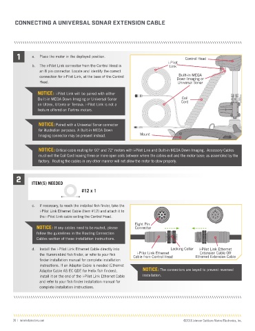
CONNECTING A UNIVERSAL SONAR EXTENSION CABLE


         1      a.   Place the motor in the deployed position.                            Control Head
                                                                                  i-Pilot
                b.  The i-Pilot Link connector from the Control Head is           Link
                    an 8 pin connector. Locate and identify the correct
                                                                                       Built-in MEGA
                    connection for i-Pilot Link, at the base of the Control           Down Imaging or
                    Head.                                                             Universal Sonar

                   NOTICE: i-Pilot Link will be paired with either
                   Built-in MEGA Down Imaging or Universal Sonar                        Coil
                   on Ultrex, Ulterra or Terrova. i-Pilot Link is not a                 Cord
                   feature offered on Fortrex motors.


                    NOTICE: Paired with a Universal Sonar connector
                    for illustration purposes. A Built-in MEGA Down
                    Imaging connector may be present instead.       Mount


                    NOTICE: Critical cable routing for 60" and 72" motors with i-Pilot Link and Built-in MEGA Down Imaging.  Accessory Cables
                    must exit the Coil Cord leaving three or more open coils between where the cables exit and the motor base; as assembled by the
                    factory.  Routing the cables in any other manner will not allow the motor to stow properly.


         2
                ITEM(S) NEEDED
                                        #12 x 1


                c.  If necessary, to reach the installed fish finder, take the
                    i-Pilot Link Ethernet Cable (Item #12) and attach it to
                    the i-Pilot Link cable exiting the Control Head.
                                                                  Eight Pin
                   NOTICE: If any cables need to be routed, please   Connector
                   follow the guidelines in the Routing Connection
                   Cables section of these installation instructions.

                d.  Install the i-Pilot Link Ethernet Cable directly into          Locking Collar  i-Pilot Link Ethernet
                                                                   i-Pilot Link Ethernet
                                                                                                 Extension Cable OR
                    the Humminbird fish finder, or refer to your fish   Cable from Control Head  Ethernet Extension Cable
                    finder installation manual for complete installation
                    instructions. If an Adapter Cable is needed (Ethernet
                    Adaptor Cable AS EC QDE for Helix fish finders),   NOTICE: The connectors are keyed to prevent reversed
                    install it on the end of the i-Pilot Link Ethernet Cable   installation.
                    and refer to your fish finder installation manual for
                    complete installation instructions.


       20  |  minnkotamotors.com                                                         ©2018 Johnson Outdoors Marine Electronics, Inc.