
Page 97 - Newham SuDS DESIGN & EVALUATION GUIDE
P. 97
Detailed Design 9.5.10 Calculation checklist Information for technical Parameter Guidance on design/calculation input Information for technical Detailed Design
assessment
Key calculation inputs and outputs should be
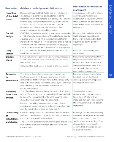
Modelling
It is not anticipated that SuDS design will require
The designer is to justify where
presented in the ‘Flows and Volumes
modelling of extensive piped systems. In some
no hydraulic modelling is
of the SuDS
checklist’ (see appendix). The following
instances where the scheme is relatively small and not undertaken. Calculations/model
layout.
checklist identifies useful calculation checks:
outputs should be provided to
hydraulically complex standard calculations will be
support the Flows and Volumes
accepted in lieu of a hydraulic model. Layout
Guidance on design/calculation input
Parameter
proforma
drawings should be clearly labelled with the
Confirm the rainfall source and
Rainfall
Outfalls into receiving sewers or watercourses can be
data is used, conversion factors should be applied to
any conversions applied to
data. FEH 2013 rainfall data preferred. Where FSR rainfall assessment Outfall numbering convention used by models. Designer is to indicate whether
at risk of surcharge and lack of free discharge due to
SuDS storage calculation is
design
bring in line with FEH rainfall data. data.
elevated water levels. This can result in additional likely to be influenced by high
Areas All area of contributing runoff should be represented Provide a drawing clearly storage being required. Free discharge should not be water levels at the point of
generating within the storage calculation. identifying the areas of surface assumed. The risk of surcharge should be assessed discharge.
runoff The designer must justify where a Cv of less than 0.9 runoff contribution within each and accounted for within calculations as appropriate.
for impermeable area is used for calculations. subcatchment. Long Long sections will allow detailed consideration of Long section showing peak
Designer to state Cvs used and section levels across the site. water levels.
justify use of Cv less than 0.9. Erosion Flows along swales (or other vegetated surfaces) are Designer to demonstrate that
Maximum Statutory authorities e.g. LLFA, sewerage undertaker, The flow control rate should be check at risk from erosion. Peak flow velocities should be they have considered risk of
flow control IDB or EA, might place restrictions on the outfall flow identified along with the less than 1 - 2 l/s. erosion and taken measures to
rate rates based on the available capacity of receiving method for defining the rate. Concentrated inlet points are also prone to erosion. safeguard scheme. Peak flow
infrastructure. velocity calculations to be
Climate CCA has been applied within calculations based on Designer to justify selection of provided as appropriate.
91 change design life of development and any applied sensitivity CCA based on development Designing The design should incorporate overflows at each Locations of overflows should 92
allowance assessment. type and design life. for SuDS component. Hydraulic calculations should be identified on the layout
Urban creep Urban creep allowance applied to non-adoptable Designer to justify selection of exceedance demonstrate that overflows have sufficient capacity to drawing along with proposed
impermeable areas on developments where permitted Urban Creep percentage deal with anticipated flow rates. SuDS layout drawing exceedance flow route.
development is likely to occur. should identify the anticipated flow route for
exceedance events.
Initial As a rule of thumb, where the area of development is Designer to confirm whether
interception no greater than 4 times the SuDS wetted area, a 5mm 5mm interception losses have Managing The FRA should identify the potential for flows from The designer should
offsite. These flows can be unpredictable and difficult
demonstrate how anticipated
losses allowance may be made for interception losses for been applied in calculation. flows from
2
each m of development. off site. to quantify. Management of flows through the site flows from off site will be
Critical A range of rainfall durations must be considered when Designer to demonstrate that should not increase flood risk elsewhere. managed through the site using
duration calculating attenuation storage. sufficient rainfall durations have Detailed modelling to establish the rates of flow the layout drawing and design
been considered to achieve anticipated would not be considered compulsory (but statement.
worst case scenario. may be required on a case by case basis).
Control of Where the designer demonstrates that water can be Designer to confirm how Consistency Detailed design of SuDS components should reflect Drawings should clearly identify
runoff ‘lost’ or stored separately Approach 1 can be applied volume of runoff has been of hydraulic calculations / hydraulic models, taking into site levels, storage locations and
volume for the control of flow being discharge from the site. controlled. calculations account slopes and low lying levels. flow controls with cross
and design. The LLFA will consider design drawings to ensure that sections and long sections. The
flow control sizing and storage provision is as per design statement should
calculations. confirm that drawings deliver
calculated volumes.
London Borough of Newham SuDS D & E Guide © 2018 McCloy Consulting & Robert Bray Associates London Borough of Newham SuDS D & E Guide © 2018 McCloy Consulting & Robert Bray Associates