
Page 5 - QR IMER COMBI-250VA
P. 5
IMER INTERNATIONAL S.p.A. GB
COMBI 250 VA
9. ELECTRICAL CONNECTION Connect the machine to the power mains and start as
described in paragraph 11.
- Ensure that voltage corresponds to machine Open the valve (ref.V fig.7) and ensure sufficient flow of
dataplate specifications. cooling water to the diamond blade.
The power supply line must be equipped with current overload Cutting
protection (e.g. thermal cutout) and protection against indirect Place the material to be cut on the cutting surface against the
contact (e.g. residual current circuit breaker). fence at the required angle using a goniometer.
Connect the machine to an efficient earthing system. Adjust the height of the cutting head by means of the
The size of the power cable wires must be based on handwheel (ref. R fig. 6).
operating current and length of the power line to prevent Ensure that the handwheels for angled cuts (ref. L fig. 7) and
excessive voltage drops (ref.Table 4). tightened fully down.
Start the saw as described in paragraph 11.
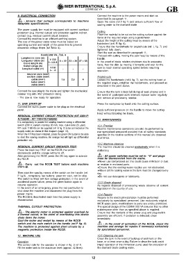
Combi 200 VA - Tab. 4 Proceed with cutting moving the saw head by means of the
handle.
Lunghez z a cavo (m) V 230 0 ÷ 22 23 ÷ 36 37 ÷ 58 In the event of blade rotation shutdown due to excessive
Longueur câble (m) I= 5.8 A -- force, free the disk by moving it forwards and wait for the
saw to reach normal operating speed before resuming
Cable length (m) 2.5 4 operation.
Kabel Länge (m) V 11 0 - Angled cuts
Longitud cable (m) I= - A Loosen the handwheels (ref.L fig. 7), set the cutting head at
the required angle, retighten the handwheels, and proceed as
sez ione cavo (mm²) 1.5 described in the point above.
section câble (mm²)
cable (mm²)
kabel (mm²)
cable (mm²)
Connect the saw plug to the mains and tighten the mechanical Ensure that the tank is kept full during all work phases and in
retainer ring with IP67 protection rating. the event of prolonged work intervals replace water regularly
and remove all processing residue.
- The saw is now ready for operation.
11. SAW START-UP Press the workpiece by hand onto the cutting surface.
Connect the mains power cable to the plug on the electrical
panel. Apply sufficient pressure on the handle to move the cutting
head without blocking the blade.
RESIDUAL CURRENT CIRCUIT PROTECTION (KIT 230V-P/
N.1169245 - KIT 110V-P/N.1169249): 13. MAINTENANCE
It is compulsory to power the sawing machine using a differential
switch (230 V; current intensity 30 mA; max. cut-in time 20 sec). 13.1 Premise
KIT code 1169245 can be supplied (ref. E fig. 2) to be connected on the Routine maintenance operations can also be performed by
supply cable as shown in the diagram (page 13). non-specialised personnel provided that all safety standards
When the KIT has been installed, press the green ON button to be able specified in the relative sections of this manual are observed
to start the sawing machine. An orange led will light up (differential at all times.
protection on).
13.2 Machine cleaning
RESIDUAL CURRENT CIRCUIT BREAKER TEST: The machine should be cleaned exclusively when it is
Press the black key TEST on the RCCB; the switch stationary.
disconnects and the orange led turns off.
After performing the TEST, press the ON key again to activate - All power switches must be set to 0 and plugs
the RCCB. must be disconnected from the mains.
- Carry out the RCCB TEST before each machine Never use compressed air; this could cause infiltration of dust
start-up. or residue in enclosed parts.
Then start the saw by means of the switch on the handle (ref. Ensure that the cooling water nozzles are not obstructed.
P fig.6) , comprising two buttons: green for start, red for stop. Above all the cooling water in the tank must be changed every
The switch is fitted with low voltage protection; in the event of day.
accidental power failure, press the green button again to Do not use detergents or lubricants.
resume operation.
In the event of an emergency, press the red pushbutton to 13.3 Waste disposal
shut down the machine and disconnect the plug from the As regards disposal of processing waste observe all current
power mains. legislation in the country of use.
The RCCB is deactivated each time the power supply is
disconnected. 13.4 Repairs
Repairs to the electrical installation must be performed
THERMAL CUTOUT PROTECTION: exclusively by specialised personnel. Use exclusively original
IMER spare parts; modifications to parts are strictly prohibited.
- The electric motor is protected against overload by The special design of the COMBI 200 VA ensures that no other
a thermal cutout; in the event of overheating this device maintenance other than as specified above is required.
shuts down the motor. Ensure that the contacts of the power plug and plug-switch
Cool the motor and restart by means of the RCCB assembly are efficient. If oxidation is detected, clean
switch and the main switch on the handle (ref.P fig. 6). immediately
The machine is protected against short circuits by a
magnetic protection inside the RCCB. - In the event of activation of the RCCB, check the
machine and arrange for repairs if necessary exclusively
by specialised personnel.
12 . MACHINE USE 13.5 Cleaning the tank
Clean the tank in the event of build-up of sediment on the
Operation base, or at least once a day. Failure to clean the tank could
The correct side for the operator is shown in fig. 3 ref X. impair operation of the immersion pump used for circulation of
Fill the water tank to the maximum level (approx. 42 litres). the diamond blade cooling water.
12