
Page 18 - 2020 7th St Presentation
P. 18
2.3' TO FACE OF SEAWALL 1.9' TO SEAWALL CAP 3.3' 80' WIDE (P) WATERWAY 3.2' WET FACE OF SEAWALL 2.2' TO FACE OF SEAWALL 1.2' WIDE CONCRETE SEAWALL CAP ELEV. = 3.8' BOUNDARY CORNER NOT FOUND OR SET FALLS IN WATER FOUND PK NAIL AND DISK- "D&W LB 6896" 0.50' SOUTH AND 2.14' WEST OF THE BOUNDARY CORNER
L:\21-134 Toscana 2231 Forrest Lane\ALD-Dwgs\21-134.dwg, Plotted on 9/12/2021 10:24:02 PM by Christian Andrea
LANDSCAPE ARCHITECTURE
N00°20'00"E 106.46' (P)
WOOD DOCK
N00°20'00"E 106.46' (M)
2780 S. Horseshoe Drive Suite 5
Naples, FL 34104
FOUND DRILL HOLE IN CONCRETE SEAWALL 0.22' NORTH AND 2.11' WEST FROM THE BOUNDARY CORNER 1.9' WIDE CONCRETE SEAWALL CAP ELEV. = 4.3' METAL PICKET FENCES SET WITNESS POINT 25.00' (C) WOOD DOCK BOAT LIFT 38.9' WATER TO BOUNDARY 2.9 3.7 3.2 25' Rear Setback 15' Pool Setback 34.6' 4.1 DAVIT ON CONCRETE 35.1' 3.6 3.2 25.00' (C) 3.2 1.6' WIDE 3.2 CONCRETE SEAWALL CAP ELEV. = 3.9' License LC26000259
(239) 430-1661
3.9
Design@ALDinc.net
Christian Andrea
WITH A/C UNIT
38.2'
WOOD DECK
3.7
ELEVATED
3.6
3.5
3.9
License No. 1178
CONCRETE POOL EQUIPMENT PAD ELEV. = 4.0' ABOVE GROUND HOT TUB AREA 6.3' SET WITNESS POINT
1.2' 7.4' 3.6
4.6 Copyright Architectural Land Design ©
3.6 20.8' 3.7
3.9
4.6 CONCRETE POOL TOP ELEV. = 4.4' BRICK POOL DECK 28.2' ELEV. = 9.8' METAL PICKET FENCE IS 0.7' SOUTH OF BOUNDARY LINE
8.9' WATER TO WATER CANITLEVERED WOOD DECK WITH A/C UNIT
3.8
7'-6" Side Setback 12.5' 13.1' 3.2' 8.1' 8.2'
BEARING BASIS N85°00'00"E 141.81' (P) N85°00'00"E 141.81' (C) 3.3' CANTILEVERED BAY WINDOW 52.0'
12.2' 43.1' 7'-6" Side Setback
LOT 20 11.1' 3.4' 4.2 CANTILEVERED WINDOW COVERED BALCONY 4.2 4.1 4.5 LOT 22
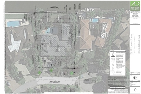
4.2 (COVERED BRICK AREA BELOW) 117.82' (M) BETWEEN MONUMENTS 2231 Forrest Lane 2231 Forrest Ln. City of Naples, FL EX. CONDITIONS PLAN
4.1 CONCRETE A/C PAD ELEV. = 4.6' 2 STORY RESIDENCE FINISHED FLOOR ELEV. = 5.3' (NAVD 1988) 4.7 4.7
authorization. Any deviations or inaccuracies need to be brought to the attention of the Owner immediately. * All base information has been provided by others, verification of setbacks, property lines, etc. need to be provided by others. * It is the Contractors responsibility to verify that he has the most current plan. * Contractor shall not scale from plan, use dimensions only. * These plans are the property of Architectural Land Design and may not be used or reproduced without This Document contains information proprietory to ARCHITECTURAL LAND DESIGN and no part of this drawing shall be reproduced or disclosed to others or used for any purpose other than that for which it was furnished, without prior written permission from ARCHITECTURAL LAND DESIGN. 4.7 4.1 BRICK WALKWAY 39.1' 13.8' 4.7 9.7'
5.1
0.5'
CONCRETE ELEV. = 4.9' Legend:
Legend:
4.1 A/C PAD GARAGE ELEV. = 4.7' 24.4' 4.9 4.1 4.6 N88°06'57"W 142.82' (C) N88°10'00"W 142.58' (P) 4.7 100'-0" Depicts Proposed Grade Information
(Reflects Finished Grade)
9.9' 4.1 4.4 29.7' 4.6 2.5' 2.0' 2.0' 2.1' 2.4' 19.4' 4.1 5' X 15' (P) UTILITY EASEMENT 100.0' Depicts Existing Grade Information
Direction of Drainage Flow
4.2
Sleeves, Sch. 40 PVC (see plans)
4.0
0.23' NORTH AND 0.24' WEST FOUND 5/8" REBAR -NO IDENTIFICATION FROM THE BOUNDARY CORNER 4.5 4.2 4.1 116.81' (M) BETWEEN MONUMENTS 30.9' 4.1 BOUNDARY CORNER NOT FOUND OR SET FALLS IN DRIVEWAY 4.2 4.3 30' Front Setback 4.4 4.4 4.3 BRICK WALKWAY 4.1 31.0' (PVC or Smooth Walled Corrugated)
4" Drain Pipe
6" Drain Pipe
(PVC or Smooth Walled Corrugated)
8" Drain Pipe
(PVC or Smooth Walled Corrugated)
Catch Basin w/ Atrium grate
(See Detail 'A' on Details Sheet)
CONCRETE 4.2 4.3 4.3 29.6' 6.4 LOT 21 (OTHER IMPROVEMENTS NOT LOCATED UNDER SCOPE OF SURVEY) 4.6 4.8 4.7 4.7 AD 10" Round Grate Connected to 8" Pipe
4.1
CB10
(See Detail 'B' on Details Sheet)
8" Round Grate Connected to 6" Pipe
3.9 4.1 CB8 (See Detail 'B' on Details Sheet)
Downspout Connected to Gutter
3.9 4.0 N01°50'00"E 72.88' (P) DS (See Detail 'C' on Details Sheet)
4.2
N02°00'46"E 72.76' (M)
3.9 CB9 9" Catch Basin
5.4 4.0
CB12 12" Catch Basin
3.7
3.8 4.2
4.7 CB18 18" Catch Basin
3.6 3.6 3.7 0'
3.6 3.5 Proposed Contour Line
BRICK DRIVE 3.6 26"
3.4 3.5 3.5 1' Existing Contour Line Drawing Date: IS 07.09.21
3.2 CROWN OF ROAD 3.4 BRICK DRIVE 5.1 3.8 50' (P) CUL-DE-SAC RADIUS Contractor to verify all quantities. Scale: 1" = 10'-0"
3.4 3.3 L1
3.3 3.3 ELEV. = 3.8' 3.4 3.5
3.1 3.1 3.4 21-134
3.5 3.3 3.3 3.2 3.3 3.2 3.2 3.2
3.3 3.5 Notes
3.3
3.5 3.5 3.4 3.4
3.5 PAVED Confirm selections with owner before ordering.
4.0 8" PVC 60' (P) RIGHT-OF-WAY N01°50'00"E 53.98' (P) N02°01'06"E 54.13' (M) Contractor to confirm quantities.
3.9 3.8 Sleeving File Name: 21-134.dwg
3.8 FORREST LANE All planter areas are to receive sleeves for irrigation and landscape lighting. Architectural Information Provided By:
File Name:
----
3.7 GRATED INLET Sleeve sizes are to be 2 sizes larger than actual pipe size. Company Name: ----
Date:
----
3.5 3.6 3.5 GRATE ELEV. = 3.2' 8" PVC INV ELEV. = 2.2' BOTTOM INV ELEV. = 1.7' Landscape Lighting Site Information Provided By: ----
BENCHMARK ELEV. = 3.51' (NAVD 1988) BENCHMARK ELEV. = 3.55' (NAVD 1988) All grades Represent Finished Grades
Company Name:
3.5 It is anticipated that Landscape lighting will be installed. File Name: ----
----
Date:
Unless Otherwise Noted (ie. 'Slab')
GRATED THROAT INLET GRATE ELEV. = 3.8' N. THROAT INV. ELEV. = 3.6' N. 8" PVC INV ELEV. = 2.0' 0 BOTTOM INV ELEV. = 1.6' Any Inconsistencies w/ these plans need to be reported to ALD and the Owner. 0
Contractor to verify property lines and setbacks before construction.
Contractor must have property lines staked and located,
and must verify plan dimensions and field conditions are consistent.
Contractor shall verify that he has the most up to date plans, and that they have been approved and accepted by the Owner before commencing construction. Contractor shall verify that he has the most up to date plans, and that they have
been approved and accepted by the Owner before commencing construction.