
Page 19 - 2020 7th St Presentation
P. 19
Index
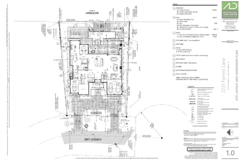
2.3' TO FACE OF SEAWALL 1.9' TO SEAWALL CAP 80' WIDE (P) WATERWAY WET FACE OF SEAWALL 2.2' TO FACE OF SEAWALL 1.2' WIDE CONCRETE SEAWALL CAP ELEV. = 3.8' BOUNDARY CORNER NOT FOUND OR SET FALLS IN WATER FOUND PK NAIL AND DISK- "D&W LB 6896" 0.50' SOUTH AND 2.14' WEST OF THE BOUNDARY CORNER A1. Mega Smooth 1953Sf
DRIVEWAY
A
L:\21-134 Toscana 2231 Forrest Lane\ALD-Dwgs\21-134.dwg, Plotted on 9/12/2021 10:24:05 PM by Christian Andrea
A2. Double 4x8 Soldier Border
A3. Single 4x8 Border
B1. Glass Tile Water Line
N00°20'00"E 106.46' (P)
E H B POOL 485Sf LANDSCAPE ARCHITECTURE
WOOD DOCK
B2. Pearl Finish 2780 S. Horseshoe Drive Suite 5
N00°20'00"E 106.46' (M)
Naples, FL 34104
B3. Spa 46Sf
FOUND DRILL HOLE IN CONCRETE SEAWALL 0.22' NORTH AND 2.11' WEST FROM THE BOUNDARY CORNER 1.9' WIDE CONCRETE SEAWALL CAP ELEV. = 4.3' METAL PICKET FENCES SET WITNESS POINT 25.00' (C) D G 25' Rear Setback 15' Pool Setback D C2 C2 25.00' (C) 1.6' WIDE CONCRETE SEAWALL CAP ELEV. = 3.9' PATIO License LC26000259
(239) 430-1661
B4. Pool Equipment Gas Heater
Design@ALDinc.net
B5. Shellstone Coping 1.5" think min sq edge
B6. Fountain Emitter Qty. 3
Christian Andrea
G
B6
C1
C2. Patio & Walkway Shellstone 12x24 216Sf
C1
3
8
3
13'-10 " POOL DECK POOL POOL DECK 10'-5 " C C1. Pool Deck Shellstone Paving 12x24 mudset 1428 Sf
8
B D RETAINING WALL (Concrete Block) License No. 1178
SPA SINK SINK D F2 Copyright Architectural Land Design ©
K F2 FIRE TABLE
36" Gas Grill W/ 36" Gas Grill W/ Hood Insert Hood Insert Above Above E
B3 OUTDOOR LIVING SET WITNESS POINT
F1 F FENCE
METAL PICKET FENCE
F1 F1. Gate (Self Latching)
A C1
1.5 IS 0.7' SOUTH OF BOUNDARY LINE F2. 4' Fence (Bronze)
K G STEPS Treads and risers to match pool coping
F.D.
F.D.
7'-6" Side Setback ACCESS H WOOD DECK
ATTIC
ATTIC
ACCESS
BEARING BASIS N85°00'00"E 141.81' (P) N85°00'00"E 141.81' (C) C.U. DW. DW. Sink Sink J GUTTER
Bar Bar 7'-6" Side Setback I PROPANE TANK (1000 Gallon)
C.U.
C.U.
C.U. DW. DW. J LOT 22 K WATER MANAGEMENT BERM
Ovens
UP. UP. Ovens
23R.@ 7.0"
23R.@ 7.0"
22T.@ 11"
22T.@ 11"
+1" NOSING
DN. +1" NOSING 01 01
DN.
23R.@ 6.95"
23R.@ 6.95"
22T@ 11"
22T@ 11"
+1" NOSING 02 02
+1" NOSING
01 01 DN DN 03 03
36"
36"
36" 36" L DRAIN SYSTEM
02 02 04 04
Ref./Freezer
Ref./Freezer Ref./Freezer
Ref./Freezer
03
05
05
03
B4 Sink Sink 04 04 06 06 117.82' (M) BETWEEN MONUMENTS 2231 Forrest Lane 2231 Forrest Ln. City of Naples, FL SITE LAYOUT AND DIMENSION PLAN
05 05 07 07
Sink Sink
06 06
JANDY 3-WAY NEVER LUBE JANDY 3-WAY NEVER LUBE
07 07 08 08 09 09 09 09 10 10 36" VERIFY MATERIALS WITH OWNER.
authorization. Any deviations or inaccuracies need to be brought to the attention of the Owner immediately. * All base information has been provided by others, verification of setbacks, property lines, etc. need to be provided by others. * It is the Contractors responsibility to verify that he has the most current plan. * Contractor shall not scale from plan, use dimensions only. * These plans are the property of Architectural Land Design and may not be used or reproduced without This Document contains information proprietory to ARCHITECTURAL LAND DESIGN and no part of this drawing shall be reproduced or disclosed to others or used for any purpose other than that for which it was furnished, without prior written permission from ARCHITECTURAL LAND DESIGN. B4 F.D. 10 10 11 11 11 11 Ref./Freezer CONTRACTOR TO CONFIRM ALL QUANTITIES.
Washer Dryer
Dryer
Washer
36"
Ref./Freezer
F.D.
ATTIC
ATTIC
ACCESS
ACCESS
3'
ENTRY
ATTIC
ATTIC
ACCESS
ACCESS
3'-6" Legend:
Legend:
3'
C1 100'-0" Depicts Proposed Grade Information
C2 3'-6" N88°06'57"W 142.82' (C) N88°10'00"W 142.58' (P) (Reflects Finished Grade)
11'-4" 3' 3' 8'-8" 3' 7'-6" C2 5' X 15' (P) UTILITY EASEMENT 100.0' Depicts Existing Grade Information
Direction of Drainage Flow
3'
20'-4"
9'
Sleeves, Sch. 40 PVC (see plans)
7'-7"
0.23' NORTH AND 0.24' WEST FOUND 5/8" REBAR -NO IDENTIFICATION FROM THE BOUNDARY CORNER 116.81' (M) BETWEEN MONUMENTS 28' 12' 20'-4" 30' Front Setback DRIVE 7'-6" MOTOR COURT A1 7'-9 " (PVC or Smooth Walled Corrugated)
1
4" Drain Pipe
4
14'-8"
20'
6" Drain Pipe
(PVC or Smooth Walled Corrugated)
26'
8" Drain Pipe
16'
MOTOR COURT
(PVC or Smooth Walled Corrugated)
Catch Basin w/ Atrium grate
(See Detail 'A' on Details Sheet)
CB10
(See Detail 'B' on Details Sheet)
5'-2 1 " CB8 8" Round Grate Connected to 6" Pipe
4' 2 3'-6" 4' AD 10" Round Grate Connected to 8" Pipe
(See Detail 'B' on Details Sheet)
4' Downspout Connected to Gutter
A2 DS (See Detail 'C' on Details Sheet)
N01°50'00"E 72.88' (P)
A2 9'-3" N02°00'46"E 72.76' (M) CB9 9" Catch Basin
Channel Drain CB12 12" Catch Basin
(Connect to Stormwater System) I
DRIVE 8 DRIVE CB18 18" Catch Basin
17'-3" 25'-3 3 " Channel Drain 0' Proposed Contour Line
(Connect to Stormwater System)
CROWN OF ROAD Contractor to verify all quantities. Scale:
A1 1' Existing Contour Line Drawing Date: IS 07.09.21
B1 50' (P) CUL-DE-SAC RADIUS 1" = 10'-0"
1.4 ELEV. = 3.8' L1
4' 21-134
4'
Notes
5
4'-7 " 4' 12' 4' 34'-6" 4' 12' 4' Confirm selections with owner before ordering.
8
8" PVC 60' (P) RIGHT-OF-WAY N01°50'00"E 53.98' (P) N02°01'06"E 54.13' (M) Contractor to confirm quantities. File Name: 21-134.dwg
PAVED
Sleeving
GRATED INLET GRATE ELEV. = 3.2' 8" PVC INV ELEV. = 2.2' BOTTOM INV ELEV. = 1.7' All planter areas are to receive sleeves for irrigation and landscape lighting. Architectural Information Provided By: ----
Company Name:
Sleeve sizes are to be 2 sizes larger than actual pipe size.
FORREST LANE
File Name:
----
Date:
----
Site Information Provided By:
Landscape Lighting
BENCHMARK ELEV. = 3.51' (NAVD 1988) BENCHMARK ELEV. = 3.55' (NAVD 1988) It is anticipated that Landscape lighting will be installed. File Name: ----
Company Name:
----
Date:
----
All grades Represent Finished Grades
Unless Otherwise Noted (ie. 'Slab')
GRATED THROAT INLET GRATE ELEV. = 3.8' N. THROAT INV. ELEV. = 3.6' N. 8" PVC INV ELEV. = 2.0' 0 BOTTOM INV ELEV. = 1.6' Any Inconsistencies w/ these plans need to be reported to ALD and the Owner. 1.0
Contractor to verify property lines and setbacks before construction.
Contractor must have property lines staked and located,
and must verify plan dimensions and field conditions are consistent.
Contractor shall verify that he has the most up to date plans, and that they have been approved and accepted by the Owner before commencing construction. Contractor shall verify that he has the most up to date plans, and that they have
been approved and accepted by the Owner before commencing construction.