
Page 22 - 2020 7th St Presentation
P. 22
2.3' TO FACE OF SEAWALL
1.9' TO SEAWALL CAP
WET FACE OF SEAWALL 2.2' TO FACE OF SEAWALL 1.2' WIDE CONCRETE SEAWALL CAP ELEV. = 3.8' BOUNDARY CORNER NOT FOUND OR SET FALLS IN WATER FOUND PK NAIL AND DISK- "D&W LB 6896" 0.50' SOUTH AND 2.14' WEST OF THE BOUNDARY CORNER
80' WIDE (P)
L:\21-134 Toscana 2231 Forrest Lane\ALD-Dwgs\21-134.dwg, Plotted on 9/12/2021 10:24:26 PM by Christian Andrea
WATERWAY
LANDSCAPE ARCHITECTURE
2780 S. Horseshoe Drive Suite 5
Naples, FL 34104
(239) 430-1661
Design@ALDinc.net
License LC26000259
N00°20'00"E 106.46' (P)
Christian Andrea
WOOD DOCK
N00°20'00"E 106.46' (M)
4.8' Proposed Seawall
Fire Table
3.9 (Granite Table Top, Cladding TBD) CBS Retaining Wall License No. 1178
2.9 3.2 (stucco clad to match building) 3.2 Copyright Architectural Land Design ©
CBS Retaining Wall (3) Steps 3.2
(stucco clad to match building) (12" Treads, 6" Risers)
5'-0" 3.2
8'-0" AD AD 8'-0" AD 6'-6" (3) Steps 15' Pool Setback 4.1 5'-0" 6'-6"
25.00' (C) 7'-10" Planter Planter 6'-6" 5'-0" 25' Rear Setback 6'-6" AD Planter AD 4'-10" 25.00' (C) 1.6' WIDE
(12" Treads, 6" Risers)
Hand Rail
8'-0"
8'-0"
CBS Retaining Wall CONCRETE SEAWALL CAP ELEV. = 3.9'
8'-0" (stucco clad to match building)
Planter
AD
POOL DECK Lighting
Lighting Planter
Pool Main Drains POOL DECK
(3' min sep, qty by code) POOL
Bench
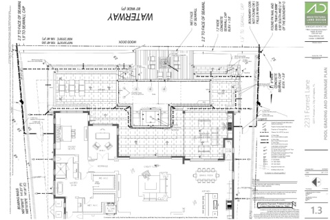
8'-0" 8'-0" 8'-0" 2231 Forrest Lane 2231 Forrest Ln. City of Naples, FL POOL GRADING AND DRAINAGE PLAN
authorization. Any deviations or inaccuracies need to be brought to the attention of the Owner immediately. * All base information has been provided by others, verification of setbacks, property lines, etc. need to be provided by others. * It is the Contractors responsibility to verify that he has the most current plan. * Contractor shall not scale from plan, use dimensions only. * These plans are the property of Architectural Land Design and may not be used or reproduced without This Document contains information proprietory to ARCHITECTURAL LAND DESIGN and no part of this drawing shall be reproduced or disclosed to others or used for any purpose other than that for which it was furnished, without prior written permission from ARCHITECTURAL LAND DESIGN. 8'-0" AD Planter AD Steps Lighting Steps Channel Drain AD Planter 8'-0" CB 4' Tall Fence
(Connect to Stormwater System)
(Aluminum, Color TBD by Owner)
CB DS 3' Wide Gate
(Aluminum, Self-Latching)
SET WITNESS POINT
4' Tall Fence SINK SINK
Legend:
(Aluminum, Color TBD by Owner) SPA Legend:
4.6
3' Wide Gate
(Aluminum, Self-Latching) 100'-0" Depicts Proposed Grade Information
(Reflects Finished Grade)
8'-0" (6) Spa Jets
3.7
Spa Drains/Vents 36" Gas Grill W/ 36" Gas Grill W/ Hood Insert Hood Insert Above Above 100.0' Depicts Existing Grade Information
3.6 8'-0.5"
3.9 Spa Controls Direction of Drainage Flow
Sleeves, Sch. 40 PVC (see plans)
OUTDOOR LIVING
4" Drain Pipe
(PVC or Smooth Walled Corrugated)
6" Drain Pipe
(PVC or Smooth Walled Corrugated)
METAL PICKET FENCE
BOUNDARY LINE
IS 0.7' SOUTH OF
8" Drain Pipe
(PVC or Smooth Walled Corrugated)
Catch Basin w/ Atrium grate
AD (See Detail 'A' on Details Sheet)
CB10 10" Round Grate Connected to 8" Pipe
(See Detail 'B' on Details Sheet)
8'-1" CB8 8" Round Grate Connected to 6" Pipe
(See Detail 'B' on Details Sheet)
4.6 8'-1" DS Downspout Connected to Gutter
(See Detail 'C' on Details Sheet)
CB DS DS CB CB9 9" Catch Basin
CB12 12" Catch Basin
3.8 8'-1" CB18 18" Catch Basin
8'-0" 0'
Proposed Contour Line
F.D.
F.D.
1' Drawing Date: IS 07.09.21
Existing Contour Line
Scale: 1/4" = 1'-0"
Contractor to verify all quantities.
7'-6" Side Setback 21-134
N85°00'00"E 141.81' (C)
Notes
N85°00'00"E 141.81' (P)
ATTIC
ATTIC
ACCESS
ACCESS
Confirm selections with owner before ordering.
BEARING BASIS
5'-6" 7'-6" Side Setback Contractor to confirm quantities.
Bar Bar File Name: 21-134.dwg
Sleeving
5'-6" All planter areas are to receive sleeves for irrigation and landscape lighting. Architectural Information Provided By: ----
Company Name:
CB DS Sleeve sizes are to be 2 sizes larger than actual pipe size.
File Name: ----
DW. DW. Date: ----
Landscape Lighting Site Information Provided By:
DS CB Company Name: ----
File Name:
----
It is anticipated that Landscape lighting will be installed. Date: ----
C.U. All grades Represent Finished Grades
C.U.
Sink Sink
4.5 Unless Otherwise Noted (ie. 'Slab') LOT 22
Contractor to verify property lines and setbacks before construction. 1.3
Contractor must have property lines staked and located,
DW. DW. and must verify plan dimensions and field conditions are consistent.
C.U.
C.U. Any Inconsistencies w/ these plans need to be reported to ALD and the Owner.
Contractor shall verify that he has the most up to date plans, and that they have
Contractor shall verify that he has the most up to date plans, and that they have been approved and accepted by the Owner before commencing construction. been approved and accepted by the Owner before commencing construction.
Ovens
UP. Ovens
UP.
23R.@ 7.0" 117.82' (M) BETWEEN MONUMENTS
23R.@ 7.0"