
Page 102 - Arch binder
P. 102
Operable Partitions
10 22 26 (10650) MODEL 3050 PART 2 - PRODUCT SPECIFICATIONS
2.13 SUSPENSION SYSTEM
2.12 CARRIER SYSTEM
A. Type H.D. Continuously Hinged / Electric Steel Wheel Carrier: A. Mounting System: The track shall be suspended by steel
3
Each Continuously Hinged / Electric panel shall be top Drop Rods, consisting of adjustable rods of grade 2, / 8" [10]
3
supported by one (1) carrier, utilizing a / 8" [16] diameter diameter threaded steel all-rod provided with / 8" [10] serrated
5
pendant bolt. steel nuts.
Each top carrier shall consist of four (4) permanently-
lubricated, precision ball bearing polished steel wheels, as
required for smooth and quiet operation. Floating bottom
carrier shall consist of two (2) offset, permanently
lubricated, precision ground ball bearing steel wheels riding
in a structural rectangular steel tube with 3/ 8" [10] diameter
steel guide rails. Carrier shall utilize a constant-force spring
allowing it to t ravel back and forth within the steel tube.
MODEL 3050 PART 3 - EXECUTION
3.01 INSPECTION 3.03 ADJUSTING AND CLEANING
A. Proper and complete preparation of the operable wall system A. The operable wall panels and track system shall be adjusted
opening shall be by others in accordance with the architectural and cleaned in accordance with KWIK-WALL's written
drawings, KWIK-WALL's shop drawings and ASTM E 557. Any instructions.
deviation of the actual opening from these specifi cations shall be
called to the attention of the architect prior to the installation of 3.04 PROTECTION
the operable wall. A. The operable wall panels shall be stored in the stacked
B. Defi ciencies in the operable wall opening shall be corrected (retracted) position prior to acceptance by the owner's
by others prior to installation of the operable wall. representative.
3.02 INSTALLATION 3.05 DEMONSTRATION
A. The operable wall system shall be installed by KWIK-WALL's A. KWIK-WALL's authorized distributor shall demonstrate
authorized distributor. proper operation and explain proper and necessary
B. The operable wall shall be installed in accordance with maintenance requirements of the operable wall system to
KWIK-WALL's written instructions, shop drawings and the owner's representative.
ASTM E 557 installation guidelines.
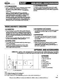
OPTIONS AND ACCESSORIES
KWIK-WALL off ers a full complement of accessories for customizing any operable
wall system to meet the specifi c needs of the most demanding project.
ACCESSORIES
3
1. Single Pass Door
EXIT 2. Pass Door Vision Lite
3. Exit Sign
4. Writing Surface
6. Panel Vision Lite
2 * 7'-0" PASS DOOR 4'-0" [1219] 7 6 4 5. Recessed Eraser Tray
1 [2134] VARIES 5 7. Tack Surface
8. Pocket Door (Not shown)
** PASS DOOR WIDTH
Notes:
1. * 7' - 8" (2.34m) minimum panel fabrication height required.
2. ** Panel width minus 12" [305] equals pass door width.
3. For complete specifi cations and details of KWIK-WALL Accessories, please visit our website at www.kwik-wall.com. 5
04-18
Dimensions in [ ] are millimeters. Contact your local distributor for additional assistance or visit www.kwik-wall.com