
Page 105 - Arch binder
P. 105
Operable Partitions
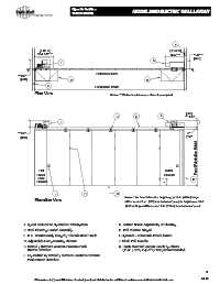
10 22 26 (10650) MODEL 3050 ELECTRIC WALL LAYOUT
F
(1.03 m) (1.04 m)
3'-4 1/2" ** 3'-5" ** 1'-6" **
[457]
A
I
C L C L
Reference Side
**1'-9"
[533] K K
E Fabrication Width
Plan View Notes: ** Minimum net clearance dimensions required.
[356]
B C A ** 1'-2"
I
**1'-2" 5"
[356] [127]
Panel Fabrication Height
Half Initial
Panel Closure
Pivot D
Closure *
J H G
Elevation View Notes: * For Panel Fabrication Heights up to 16'-0" (4.88 m) hinges
7
will be located 9 / 8" [251] from bottom of panel, for heights over 16'-0"
(4.88 m) hinges will be located 7'-0" (2.13 m) from bottom of panel.
A. Speed Reducer or Hydraulic Drive System G. Bottom Seals: Adjustable, or Floating
B. Steel Floating Carrier Assembly H. Full Mortise Hinged
C. H.D. Continuously Hinged / Electric Steel Track I. Optional - Automatic Final Closure
D. Adjustable-Compensating Closure J. Flush Pull Handle
E. Extend / Retract Constant-Pressure Push K. Flush Mounted Access Panels by others
Button Switches (2'-0" (.61m) x 4'-0" (1.22m) recommended)
F. Key Switch w/ Extend / Retract Constant-Pressure
Push Button Switches
8
04-18
Dimensions in [ ] are millimeters. Contact your local distributor for additional assistance or visit www.kwik-wall.com