Page 21 - Priesgaisrine signalizacija FX 3NET_Schneider Electric_Projktavimo instrukcija_ENG
P. 21
Planning Instruction 66571758GB0 Fire Detection 21
6.2 Detection zones
Detectors in a fire detection system are usually grouped into ‘detection zones’. In conventional systems, the
detection circuit coincides with a detection zone, but in addressable systems such as the FX 3NET, the detectors
are grouped by the software. The zones are identified by a four-digit number in the range 0001 … 9999 and they
have to be consecutive within an FX panel.
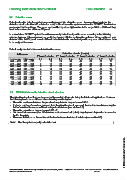
In a standalone FX 3NET system the addresses are by default assigned to zones according to the following
scheme; however, this assignment can easily be changed with the configuration software. When configured, any
detector within the FX panel, even in different detection circuits, can be assigned to any zone. All addresses have
to be assigned to a zone.
Default assignment of addresses into detection zones:
Detection circuits (Loops)
Addresses st nd rd th
1 Loop Controller 2 Loop Controller 3 Loop Controller 4 Loop Controller
Low range High range L 1 L 2 L 3 L 4 L 5 L 6 L 7 L 8
001 … 016 201 … 216 1 11 21 31 41 51 61 71
017 … 032 217 … 232 2 12 22 32 42 52 62 72
033 … 048 233 … 248 3 13 23 33 43 53 63 73
049 … 064 249 … 264 4 14 24 34 44 54 64 74
065 … 080 265 … 280 5 15 25 35 45 55 65 75
081 … 096 281 … 296 6 16 26 36 46 56 66 76
097 … 112 297 … 312 7 17 27 37 47 57 67 77
113 … 128 313 … 328 8 18 28 38 48 58 68 78
129 … 144 329 … 344 9 19 29 39 49 59 69 79
145 … 159 345 … 359 10 20 30 40 50 60 70 80
6.3 FX-SLC Addressable detection circuit structure
The detection circuit cabling can be arranged in a variety of lay-outs, being flexible for all applications. However,
the following has to be considered when selecting a cable lay-out.
The cable resistance between the panel and any detector may not exceed 60 .
If a large number of sounders, powered from the detection circuit, are used, the maximum resistance may be
further restricted to ensure sufficient voltage to all devices (see section 6.6).
The cable capacitance may not exceed 360 nF.
Not more than one zone (max. 32 detectors and/or manual call points) may drop out of operation in case of a
fault in the cable.
There are limitations on the number of devices between short circuit isolators (see section 6.5).
Note! Use the system capacity calculation tool.
© 2009 Schneider Electric. All rights reserved.
Schneider Electric Pelco Finland Oy Kalkkipellontie 6, 02650 Espoo, Finland Telephone: +358 10 446 511 Fax: +358 10 446 5103 www.pelco.com/nordic
Document Number 66571758GB0 49 2011