
Page 22 - REVISED GP Fall 2021 - ready for posting
P. 22
Looking Back At An Implant Concept From 55 Years Ago
By James R. Keenan, DDS, MS, MAGD
Dating back to my days in dental school, I and a “stud.” The insert a shoulder to serve as a stop. A
have had a hobby of acquiring “vintage” or (Figure 2) was a precision radiograph was taken with the
“antique” dentist-related items on eBay. My spiral of stainless steel No. 5 carbide bur at minimum
initial interest and auction purchases were wire, which formed inter- depth to evaluate direction and
early 1900 dental advertisements, which nal and external threads. parallelism. A bone drill (Figure
progressed to tooth powder tins, then onto Upon implantation, the 5) in a contra-angle was used to
“vintage” or “antique” dental instruments insert would be held in enlarge the opening to the size
and miscellaneous items. Last year, one place due to the later- necessary for tapping. The cut-
item that sparked my interest and in which I Figure 2. Heli al pressure of the wire. ting head of the drill was equiv-
®
eventually had a winning bid was Heli Coil Coil insert. The stud (Figure 3) was alent to the depth corresponding
Implant. Rather than simply placing my new also composed of stain- to the length of the insert. A ra-
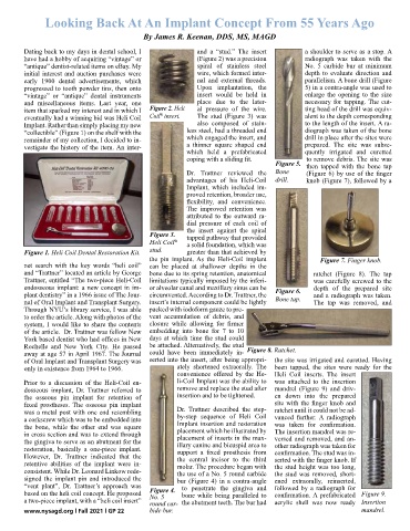
“collectible” (Figure 1) on the shelf with the less steel, had a threaded end diograph was taken of the bone
remainder of my collection, I decided to in- which engaged the insert, and drill in place after the sites were
vestigate the history of the item. An inter- a thinner square shaped end prepared. The site was subse-
which held a prefabricated quently irrigated and curetted
coping with a sliding fit. to remove debris. The site was
Figure 5. then tapped with the bone tap
Dr. Trattner reviewed the Bone (Figure 6) by use of the finger
advantages of his Heli-Coil drill. knob (Figure 7), followed by a
Implant, which included im-
proved retention, broader use,
flexibility, and convenience.
The improved retention was
attributed to the outward ra-
dial pressure of each coil of
the insert against the spiral
Figure 3. tapped pathway that provided
Heli Coil a solid foundation, which was
®
Figure 1. Heli Coil Dental Restoration Kit. stud. greater than that achieved by
the pin implant. As the Heli-Coil implant Figure 7. Finger knob.
net search with the key words “heli coil” can be placed at shallower depths in the
and “Trattner” located an article by George bone due to its spring retention, anatomical ratchet (Figure 8). The tap
Trattner, entitled “The two-piece Heli-Coil limitations typically imposed by the inferi- was carefully screwed to the
endosseous implant: a new concept in im- or alveolar canal and maxillary sinus can be Figure 6. depth of the prepared site
plant dentistry” in a 1966 issue of The Jour- circumvented. According to Dr. Trattner, the and a radiograph was taken.
nal of Oral Implant and Transplant Surgery. insert’s internal component could be lightly Bone tap. The tap was removed, and
Through NYU’s library service, I was able packed with iodoform gauze to pre-
to order the article. Along with photos of the vent accumulation of debris, and
system, I would like to share the contents closure while allowing for firmer
of the article. Dr. Trattner was fellow New embedding into bone for 7 to 10
York based dentist who had offices in New days at which time the stud could
Rochelle and New York City. He passed be attached. Alternatively, the stud Figure 8. Ratchet.
away at age 57 in April 1967. The Journal could have been immediately in-
of Oral Implant and Transplant Surgery was serted into the insert, after being appropri- the site was irrigated and curetted. Having
only in existence from 1964 to 1966. ately shortened extraorally. The been tapped, the sites were ready for the
convenience offered by the He- Heli Coil inserts. The insert
Prior to a discussion of the Heli-Coil en- li-Coil Implant was the ability to was attached to the insertion
dosseous implant, Dr. Trattner referred to remove and replace the stud after mandrel (Figure 9) and driv-
the osseous pin implant for retention of insertion and to be tightened. en down into the prepared
fixed prostheses. The osseous pin implant site with the finger knob and
was a metal post with one end resembling Dr. Trattner described the step- ratchet until it could not be ad-
a corkscrew which was to be embedded into by-step sequence of Heli Coil vanced further. A radiograph
the bone, while the other end was square Implant insertion and restoration was taken for confirmation.
in cross section and was to extend through placement which he illustrated by The insertion mandrel was re-
placement of inserts in the max-
versed and removed, and an-
the gingiva to serve as an abutment for the illary canine and bicuspid area to other radiograph was taken for
restoration, basically a one-piece implant. support a fixed prosthesis from confirmation. The stud was in-
However, Dr. Trattner indicated that the the central incisor to the third serted with the finger knob. If
retentive abilities of the implant were in- molar. The procedure began with the stud height was too long,
consistent. While Dr. Leonard Linkow rede- the use of a No. 5 round carbide the stud was removed, short-
signed the implant pin and introduced the bur (Figure 4) in a contra-angle ened extraorally, reinserted,
“vent plant”, Dr. Trattner’s approach was to penetrate the gingiva and followed by a radiograph for
based on the heli coil concept. He proposed Figure 4. bone while being paralleled to confirmation. A prefabricated Figure 9.
a two-piece implant, with a “heli coil insert” No. 5 the abutment teeth. The bur had acrylic shell was now ready Insertion
round car-
www.nysagd.org l Fall 2021 l GP 22 bide bur. mandrel.