
Page 619 - UK Air Operations Regulations 201121
P. 619
~ Regulation NCC - ANNEX VI - Non-Commercial Complex Operations n trik
panel for use by the flight crew to operate the aeroplane; and
(3) any dedicated parameters related to novel or unique design or operational
characteristics of the aeroplane as determined by the Agency.
(c) The parameters to be recorded should meet the performance specifications (range,
sampling intervals, accuracy limits and resolution in read-out) as defined in the relevant
tables of EUROCAE Document 112A, or any later equivalent standard produced by
EUROCAE.
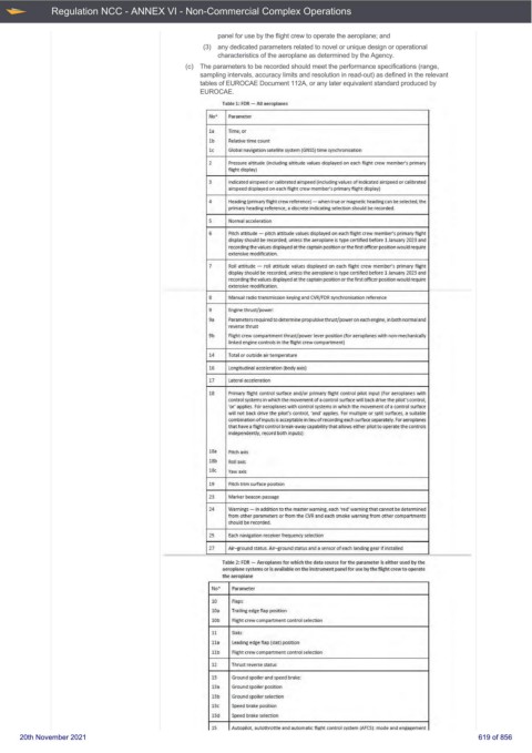
Table 1: FOR - All aeroplanes
No' Parameter
la Time; or
lb Relative time count
le Global navigation satellite system (GNSS) time synchroni.sation
2 Pressure altitude (ind uding altitude values displayed on each Hight crew member's primary
flight d isplayJ
3 Indicated airspeed or calibrated ai rspeed ( inclu dirlg va rues of indicated airspeed or calibrated
airspeed displayed on eadl flight crew member's primary flight display)
4 Heading (primary fl ight crew reference) - when true or magnetic heading can be selected, the
primary heading reference, a discrete indicating selection should be recorded.
5 Nomial acceleration
6 Prt:ch attitude - pitch attitude values displayed on each flight crew member's primary flight
display should be recorded, unless the aeroplane is type cenified before 1 January 2023 and
recording the values displayed at the captain posrt:ion or the first officer position wou Id require
extensive modification.
7 Roll attitude - roll attitude values displayed on each flight crew member's primary flight
display should be recorded, unless the aeroplane is type certified before 1 January 2023 and
recording the values displayed at the captain posrt:ion or the first officer position wou Id require
extensive modification.
8 Manual radio transmission keying and CVR/FOR synchron isation reference
9 Engine thrust/ power:
9a Pa rameters required to determine propulsive thrust/power on each engine, in both normal and
reverse thrust
9b Right crew compartment thrust/power lever position (for aeroplanes with non-medlanically
linked engine controls in the fl ight crew companment)
14 Tota l or outside air temperature
16 Longrt:udinal acceleratkm (body axis)
17 Lateral acceleration
18 Primary flight control surface and/or primary flight control pilot input (For aeroplanes with
control systems in which the movement of a control surface w ill back drive the pilot's control,
'or' applies. For aeroplanes wrt:h control systems in wtlich the movement of a control surface
will not back drive the pilot's control, 'and' applies. For multiple or spl it surfaces, a su itable
combination of inputs is acceptable in lieu of recording each surface separatety_ For aeroplanes
that have a flight control b reak-awaycapabilitythat alloW5 either pilot to operate the controls
independently, record both inputs):
18a Prt:ch axis
18b Roll axis
18c Yaw axis
19 Pitch trim surface position
23 Mark.er beacon passage
24 Warn ings - in addition to the master warning, each 'red' warning that cannot be determined
from other para meters or from the CVR and each smoke warning from other compartments
should be recorded.
25 Each navigation receiver frequency selection
27 Air-ground status. Air-ground status and a sen.sor of eadl landing gear if installed
Table 2: FOR - Aerop lanes for wtl ich the data source for t he parameter is either used by the
aeroplane systems or is available on the instrument panel for use by the flight crew to operate
the aeroplane
No' Paramet er
10 Flaps:
10a Trailing edge flap position
10b Flight crew ccxnpanment control selection
11 Slats:
ll a Leading edge flap (slat) positioo
llb Flight crew ccxnpanment control selection
12 Th rust reverse status
13 Ground spoiler and speed brake:
13a Ground spoiler position
13b Ground spoiler selection
13c Speed brak.e position
13 d Speed brakes.election
15 Autopilot, autothrottle and automatic flight control system (AFCS}: mode and engagement
20th November 2021 619 of 856