
Page 126 - Libro 2
P. 126
106
PART 2 — CEREBROVASCULAR
Figure 7-16 Temporal approach with transducer oriented in a cross-sectional plane and the orientation marker oriented toward the nose.
The transducer is positioned in cross section with the orientation marker oriented anteriorly or toward the patient’s nose (Fig. 7-16). The grayscale image presents a cross-sectional view of the brain. The su- perficial portion of the image shows the ipsilateral ce- rebral hemisphere, and the deep portion of the image shows the contralateral cerebral hemisphere. Anterior is to the left of the screen, and posterior is to the right.
Identifying the Window Using B-Mode Landmarks
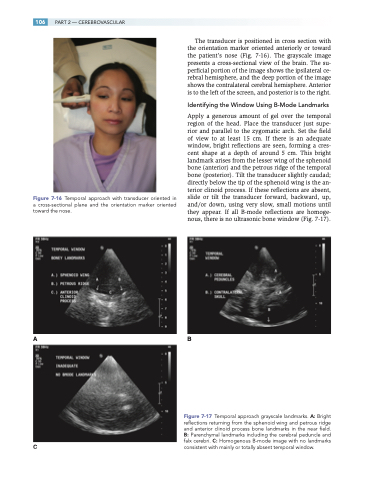
Apply a generous amount of gel over the temporal region of the head. Place the transducer just supe- rior and parallel to the zygomatic arch. Set the field of view to at least 15 cm. If there is an adequate window, bright reflections are seen, forming a cres- cent shape at a depth of around 5 cm. This bright landmark arises from the lesser wing of the sphenoid bone (anterior) and the petrous ridge of the temporal bone (posterior). Tilt the transducer slightly caudad; directly below the tip of the sphenoid wing is the an- terior clinoid process. If these reflections are absent, slide or tilt the transducer forward, backward, up, and/or down, using very slow, small motions until they appear. If all B-mode reflections are homoge- nous, there is no ultrasonic bone window (Fig. 7-17).
AB
Figure 7-17 Temporal approach grayscale landmarks. A: Bright reflections returning from the sphenoid wing and petrous ridge and anterior clinoid process bone landmarks in the near field. B: Parenchymal landmarks including the cerebral peduncle and falx cerebri. C: Homogenous B-mode image with no landmarks
C consistent with mainly or totally absent temporal window.
