
Page 129 - Libro vascular I
P. 129
Chap-09.qxd 29~8~04 14:46 Page 120
120
PERIPHERAL VASCULAR ULTRASOUND
CFA
CIA
EIA
IIA
AB
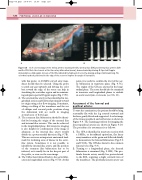
Figure 9.8 A: A color montage of the inflow arteries showing the CIA, external iliac (EIA) and internal iliac arteries (IIA)
and the CFA. Note the stenosis at the iliac artery bifurcation (arrow), demonstrated by aliasing. B: Spectral Doppler demonstrates a high-grade stenosis of the EIA, indicated by high systolic velocity, aliasing and spectral broadening. The color box has been positioned to the edge of the sector to improve the angle of insonation.
with this probe. A 3.5MHz curved array trans- ducer should then be selected. Using the probe to push any gas upwards and driving the color box toward the edge of the sector can help in visualizing the aortoiliac region and in maintain- ing adequate spectral Doppler angles (Fig. 9.7D).
2. The external iliac artery is then identified in lon- gitudinal section and followed proximally toward its origin using color flow imaging. Sometimes, tilting or rolling of the transducer and the use of oblique and coronal probe positions along the abdominal wall are useful in imaging around areas of bowel gas.
3. The common iliac bifurcation should be identi- fied by locating the origin of the external iliac and internal iliac arteries. This can be achieved in the longitudinal plane, but transverse imaging is also helpful for confirmation if the image is adequate, as the internal iliac artery usually divides in a posteromedial direction (Fig. 9.7B). This area serves as an important anatomical land- mark for localizing areas of disease in the aorto- iliac system. Sometimes it is not possible to identify the internal iliac artery, and the position of the common iliac bifurcation has to be inferred, as it usually lies in the deepest part of the pelvis, as seen on the scan image.
4. TheCIAisthenfollowedbacktotheaorticbifur- cation in longitudinal section (Fig. 9.7D). At this
point, it is useful to confirm the level of the aor- tic bifurcation in transverse plane (Fig. 9.7C). The origins of the CIA are assessed in the longi- tudinal plane. The aorta should also be examined in transverse and longitudinal planes to exclude an aortic aneurysm or stenosis (see Ch. 11).
Assessment of the femoral and
popliteal arteries
To start the examination, the patient should be lying reasonably flat with the leg rotated outward and the knee gently flexed and supported. A color image of the femoropopliteal and calf arteries is shown in Figure 9.9. The scanning positions for imaging the femoropopliteal arteries are shown in Figure 9.10. The procedure for assessment is as follows:
1. The CFA is identified in transverse section with a 5MHz, or broadband equivalent, flat linear array transducer at the groin and followed distally to demonstrate the femoral bifurcation (Figs 9.6 and 9.10A). The CFA lies lateral to the common femoral vein (Fig. 9.6).
2. Turning to a longitudinal plane, the femoral bifurcation is examined (Fig. 9.10B). The pro- funda femoris artery usually lies posterolateral to the SFA, requiring a slight outward turn of the transducer. The profunda femoris artery can
