
Page 18 - Libro vascular I
P. 18
Chap-02.qxd 29~8~04 13:19 Page 9
of these frequencies. Figure 2.4A provides an example of a continuous signal consisting of a sin- gle frequency. As only one frequency is present in the signal, the frequency spectrum displays a single line at that frequency (Fig. 2.4B). Figure 2.4C, E and G give examples of three differently shaped signals along with their frequency spectra (Fig. 2.4D, F and H), showing the range of frequencies present in each of the different signals. As ultrasound imag- ing uses pulsed ultrasound, the transducer is not transmitting a single frequency but a range of frequencies.
Beam shape
The shape of the ultrasound beam produced by a transducer will depend on the shape of the element(s), on the transmitted frequency and on whether the beam is focused. The shape of the beam will affect the region of tissue that will be insonated and from which returning echoes will be received. Multi-element array transducers use sev- eral elements to produce the beam, as discussed later in this chapter.
INTERACTION OF ULTRASOUND WITH
SURFACES
The creation of an ultrasound image depends on the way in which ultrasound energy interacts with the tissue as it passes through the body. When an ultrasound wave meets a large smooth interface between two different media, some of the energy will be reflected back, and this is known as specu- lar reflection. The relative proportions of the energy reflected and transmitted depend on the change in the acoustic impedance between the two materials (Fig. 2.5). The acoustic impedance of a medium is the impedance (similar to resistance) the material offers against the passage of the sound wave through it and depends on the density and compressibility of the medium. The greater the change in the acoustic impedance, the greater the proportion of the ultrasound that is reflected. There is, for example, a large difference in acoustic impedance between soft tissue and bone, or between soft tissue and air, and such interfaces will produce large reflections. This is the reason why ultrasound cannot be used to image beyond lung
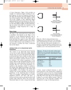
Tissue boundary between tissues of similar acoustic impedance
Tissue boundary between tissues of different acoustic impedance
When the ultrasound beam meets a boundary between two media, some of the ultrasound will be transmitted and some will be reflected. A: When the two media have similar acoustic impedances, the majority of the ultrasound will be transmitted across the boundary. B: When the two media have different acoustic impedances, most of the ultrasound will be reflected.
ULTRASOUND AND IMAGING
9
A
B
Figure 2.5
Table 2.2 The ratio of reflected to incident wave amplitude for an ultrasound beam perpendicular to different reflecting interfaces (after McDicken 1981, with permission)
Reflecting interface
Muscle/blood Soft tissue/water Fat/muscle Bone/muscle Soft tissue/air
Ratio of reflected to incident wave amplitude
0.03 0.05 0.10 0.64 0.9995
or bone, except in limited situations, as only a small proportion of the ultrasound is transmitted. It is also the reason for the loss of both imaging and Doppler information beyond calcified arterial walls (Fig. 8.26), bone (Fig. 10.12) and bowel gas, leading to an acoustic shadow beyond. Table 2.2 shows the ratio of the reflected to incident wave amplitude for a range of reflecting interfaces.
