
Page 26 - Libro vascular I
P. 26
Chap-02.qxd 29~8~04 13:20 Page 17
ULTRASOUND AND IMAGING
17
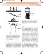
Wavelets Wavefront
Wavelets Wavefront
Focus
A: Introducing a time delay between exciting consecutive elements within the array causes the wavelets to interfere in such a way that the beam
is steered away from the path perpendicular to the transducer face (e.g., steered left or right). B: Delays between excitation of the elements in the array can be used to focus the beam.
wavefronts produced will interfere in such a way that the beam is no longer perpendicular to the front of the transducer. The angle at which the beam is produced will depend on the delay between the excitation pulses of the different elements. By changing the delay between each set of excitation pulses, it is possible to steer the beam through a range of angles from left to right.
Ultrasound beams
Vessel wall
Compound scanning sums several images obtained with the ultrasound beam steered at slightly
different angles, to improve imaging of boundaries that are perpendicular to the transducer face and to reduce noise and speckle.
A
Figure 2.16
Phased array transducers use a smaller array of elements and electronically steer the beam in this way to produce a sector image (Fig. 2.13C). This type of transducer produces a large field of view compared with the size of the transducer face, also known as the transducer footprint. Phased array transducers are used, in particular, in cardiac ultra- sound, as the heart can only be imaged through small spaces between the ribs, thus requiring a transducer with a small footprint to image a large field of view at depth. Beam steering is also used in linear array transducers when a beam that is not perpendicular to the transducer face is required, such as in Doppler ultrasound (see Chs 3 and 4) and in compound imaging. In compound imaging, the target is insonated several times with the beam steered at several different angles (Fig. 2.16). The returning echoes from these different imaging beams are combined to produce a single image. This gives improved imaging of interfaces that are not parallel to the transducer face, such as the lat- eral walls of a vessel, and reduces noise and speckle. Figure 2.17 shows the improvement in the image that can be provided when imaging a carotid plaque with compound imaging compared to conventional imaging.
B
Figure 2.15
