
Page 27 - Libro vascular I
P. 27
Chap-02.qxd 29~8~04 13:20 Page 18
18
PERIPHERAL VASCULAR ULTRASOUND
}Beam-former delays
A
B
plaque (B) compared to conventional imaging (A).
FOCUSING THE BEAM
The ultrasound beam can be focused to improve the image quality within the focal zone. By using several elements, excited with a range of delays, it is possible to focus the beam. Figure 2.15B shows how, if the elements at each end of the group of active elements are excited first, with the next two elements being excited after a short delay, and so forth, the wavelets will interfere to produce a con- cave wavefront causing the beam to converge at the focal point. The distance of the focal point from the front of the transducer is governed by the
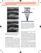
Figure 2.18 Introducing delays before summing the signals received at different elements allows dynamic focusing of the received beam. In this case, dynamic focusing allows the signals that have travelled farther along path B to be added to the signal that has travelled along path A by delaying the signal received by the middle element before summing it with the signals received by the outer elements.
BAB
length of the delays, with longer delays producing a shorter focal length.
Many modern scanners use multiple zone focus- ing whereby the image will be created in zones, using different focal lengths for different depths. The upper portion of the image, near to the trans- ducer, will be produced using a short focal length, a second set of scan lines with a longer focal length will be used for the next zone of the image, and so on. The advantage is that image quality is improved throughout the image; however, the disadvantage is that the frame rate is reduced by a factor of 1/(number of focal zones).
The focus of the beam can also be altered during reception. This is known as dynamic focusing. In this case, delays are introduced between consecutive elements on reception, rather than transmission, before the received signals are summed together. With regard to Figure 2.18, dynamic focusing allows the signals that have travelled farther along
Images showing the improvement that can be provided by compound imaging of a carotid artery
Figure 2.17
