
Page 29 - Libro vascular I
P. 29
Chap-02.qxd 29~8~04 13:20 Page 20
20
PERIPHERAL VASCULAR ULTRASOUND
Slice thickness
Axial
Figure 2.21 Resolution of a transducer can be described in different planes—axial and lateral. The slice thickness of the beam relates to the width of the beam in the non-imaging plane and governs the thickness of the slice of tissue being imaged.
incorporating a fixed lens into the front face of the transducer or by electronic focusing using a 2D array of elements, which allows focusing in both the imaging plane and the plane at right angles to the image. These 2D arrays are often called 112⁄ D arrays as there are relatively few elements along the width of the array compared with the length.
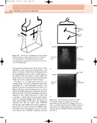
Resolution of an ultrasound system can be assessed using a test object consisting of fine wires embedded in a tissue-mimicking material. The groups of six wires are positioned so the wires are at different distances apart, allowing the user to assess what is the smallest separation at which the wires can still be resolved. The tissue-mimicking material is designed to have similar attenuation to tissue and to produce a similar back-scattered signal. Figure 2.22A is a schematic diagram of the wires in the test object and in Figure 2.22B and C the images are obtained from the test object with 2.25 MHz phased array and 10MHz linear array transducers, respectively. It can be seen that the 10 MHz trans- ducer gives better axial resolution, as all six wires are seen, whereas the 2.25 MHz transducer provides
A
Lateral
Tissue equivalent gel
Six fine wires
cm scale
12 cm penetration
cm scale
3cm penetration
Assessing ultrasound axial resolution. A: Schematic diagram of a group of six unevenly
spaced wires in a test object. B, C: Images of the test object in (A) obtained with 2.25 and 10 MHz transducers, respectively. The 10 MHz transducer gives better axial resolution and the 2.25 MHz transducer provides better penetration.
2.25 MHz
Five wires seen
B
10 MHz
Six wires seen
C
Figure 2.22
