
Page 67 - Hydra-matic 6 Speed RWD Technician's Guide (October 2005)
P. 67
54
(51)
ASSEMBLY
➤
1-2-3-4 AND 3-5
REVERSE CLUTCH
(67)
CENTER
SUPPORT
ASSEMBLY
➤ ➤ ➤ ➤ DRIVEN (52) (1) CONVERTER CARRIER TORQUE POWER FROM 2a 1
INPUT
ASSEMBLY
CLUTCH
APPLIED
➤
3-5 REVERSE
➤ DRIVING GEAR INTERNAL INPUT 2
➤ ➤
APPLIED
CLUTCH
LOW AND
REVERSE
(52)
INPUT
DRIVEN
➤
CARRIER
ASSEMBLY
(487)
DRIVING
(53)
➤ ➤ APPLIED APPLIED CLUTCH REVERSE 3-5 REVERSE 3 5 REVERSE
HELD
INPUT
FRONT SUN GEAR
OUTPUT CARRIER
➤
SUN GEAR
(68)
HELD
CARRIER
OUTPUT
ASSEMBLY
CLUTCH
LOW AND
Figure 49
➤
GEAR
INPUT
DRIVING
INTERNAL
➤
➤
(56)
4-5-6
SHAFT)
CLUTCH
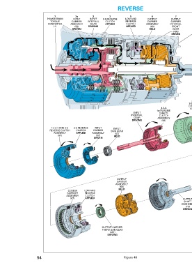
➤ in the Reverse position. • ASSEMBLY DIFFERENTIAL POWER TO and also reverses the direction of input torque for a reverse gear shaft and rear axle. The planetary gearset operates in reduction torque converter and transmission gearsets to the vehicle’s drive DRIVEN (495) GEAR HELD (68) FRONT ASSEMBLY CARRIER SPRAG OUTPUT OUTPUT CLUTCH 6 1-2-3-4 LOW REVERSE
ASSEMBLY
(w/TURBINE
7
GEAR
FRONT
OUTPUT
CARRIER
INTERNAL
➤
(70)
SHAFT
DRIVEN
OUTPUT
ASSEMBLY
(64)
2-6 AND
ASSEMBLY
4
3-5 REVERSE
CLUTCH HUB
(487)
SUN
CARRIER
DRIVING
3
7
6
5
4
1
2/2a
CLUTCH
engine braking.
CLUTCH
3-5 REV.
APPLIED
reverse direction.
shaft but in reduction.
4-5-6
CLUTCH
ratio of approximately 3.064:1.
2-6
3-5 Reverse Clutch Applied
CLUTCH
driven by the converter turbine.
the output carrier assembly (68).
Power from Torque Converter
Output Carrier Assembly Held
Low and Reverse Clutch Applied
internal front gear in a reverse direction.
APPLIED
CLUTCH
LOW & REV.
Output Carrier Front Sun Gear Driving
drives the output carrier front sun gear (487).
Output Carrier Internal Front Gear Driven
and drive the output carrier front internal gear (495).
Input Internal Gear Driving/ 2a Input Carrier Driven
The low and reverse clutch is applied and holds the low
clutch sprag assembly (467) outer race which is splined to
to the front pinion gears. The pinion gears are in mesh with
transmission down to input speed. This is referred to as
shaft. The engine then works as a brake, slowing the
With the low and reverse clutch holding the output carrier
When the throttle is released in Reverse, power from the
vehicle (output shaft) drives through the output carrier and
input carrier faster than engine speed is driving the turbine
assembly, the front pinion gears drive the output carrier
The output carrier internal front gear is splined to the output
shaft assembly (70), thus the output shaft is also driven in a
input internal gear drives the input carrier pinion gears which
rotate around the stationary input sun gear (53) thus driving
In Reverse (R), torque from the engine is multiplied through the
clutch housing which contains the input internal gear. The
The manual shift shaft (508) and the manual valve (354) are
The turbine shaft with the 4-5-6 clutch assembly (56) is
The power flows through the turbine shaft into the 4-5-6
the 2-6 and 3-5 reverse clutch hub assembly (64), which
Engine torque is transferred from the 1-2-3-4 and 3-5 reverse
clutch housing, through the output carrier front sun gear and
The 3-5 reverse clutch plates (402-403) are applied and hold
the input carrier assembly (52) in reduction. The input carrier
is splined to the 1-2-3-4 and 3-5 reverse clutch assembly
(51), which is rotating in the same direction as the turbine
54A