
Page 10 - cortex-user-guide-276-1604
P. 10
CORTEX Microcontroller and Joystick User Guide
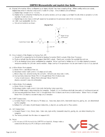
10. Digital Information: When configured as an input, digital lines have a weak pull-up. When configured as an output,
digital lines drive 0 volts for a low and 3.3 volts for a high. Circuit details are as follows:
a. Digital input range is 0 to +5 volts.
b. Digital drive is primarily limited by the 1k series resistor, so it can output a 2v high into 2k-ohms to ground or a 0.8v
low into 7k-ohms to 3.3v.
c. Digital inputs also have a 1000 pF capacitor to ground on the processor side of the 1k resistor.
d. 3 dB input bandwidth: 16 kHz.
e. Circuit connections as shown.
Digital Port
3.3 V
Weak Pull-up
In Processor
1 K
Digital Input Output
1000 PF
11. Circuit details of the Digital-to-Analog Port, SP:
a. Circuit SP is connected to the Digital-to-Analog-Converter (DAC) output of the User Processor.
b. Factory default Hex file does not support the DAC output. Check your compiler for availability and use.
c. SP is an Analog Output when configured by compiler. Drive is primarily limited by a 5 kilo-ohm internal processor
resistance and by the 100 ohm series resistor. Output swing of the processor into an open load is 0.2v to 3.1v, typical.
12. 2-Wire Motor Port outputs:
a. Motor Port 1 and Motor Port 10.
b. Maximum motor stall current: 3.0 amps at 8.5 volts.
c. Motor chop rate: determined by the compiler. Default code chop rate: 1 kHz.
d. Overcurrent protection: Motor Port 1 through Motor Port 5 shares one
4 amp circuit breaker. Motor Port 6 through Motor Port 10
shares a second 4 amp circuit breaker.
13. 3-Wire Motor Port outputs:
a. Motor Ports 2 through 9.
b. Maximum motor stall current: internally limited by motor assembly.
c. Motor PWM output: determined by the compiler. Default is 1 to 2 milliseconds high time and a 17 millisecond period.
d. Overcurrent protection: Motor Port 1 through Motor Port 5 shares one 4 amp circuit breaker. Motor Port 6 through
Motor Port 10 shares a second 4 amp circuit breaker.
14. UART Connections:
a. Ground, Power (+5v), RX data in, TX data out. Data rate, byte width, (transmit) stop bits, parity, etc. are determined
by the compiler.
b. Default for LCD data: 19,200 baud, 8 data bits, 1 stop bit, no parity and no flow control.
15. I2C Connections:
a. Ground, Power (+5v), Clock, Data. Data rate, byte width, (transmit) stop bits, parity, etc. are determined by the
compiler.
b. The factory default Hex file does not support I2C.
16. Notes:
a. Do not use a USB Hub with the CORTEX or Joystick. Always make a
connection directly to a PC USB port when needed.
Page 10 of 10