
Page 35 - Programmable Logic Controllers, Fifth Edition Mobile 2
P. 35
CHAPTER 1 PROBLEMS
1. Given two single-pole switches, write a program 5. Write a program for the relay ladder diagram
that will turn on an output when both switch A and shown in Figure 1-31.
switch B are closed.
2. Given two single-pole switches, write a program
that will turn on an output when either switch A or 120 VAC
switch B is closed. PB1
3. Given four NO (Normally Open) pushbuttons (A- S1 PS1 TS1 L1
B-C-D), write a program that will turn a lamp on if S2
pushbuttons A and B or C and D are closed. S3
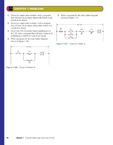
4. Write a program for the relay ladder diagram
shown in Figure 1-30.
Figure 1-31 Circuit for Problem 5.
120 VAC
S1 LS1
L1
LS2
Figure 1-30 Circuit for Problem 4.
16 Chapter 1 Programmable Logic Controllers (PLCs)
pet73842_ch01_001-016.indd 16 03/11/15 7:09 PM