Page 39 - Programmable Logic Controllers, Fifth Edition Mobile 2
P. 39

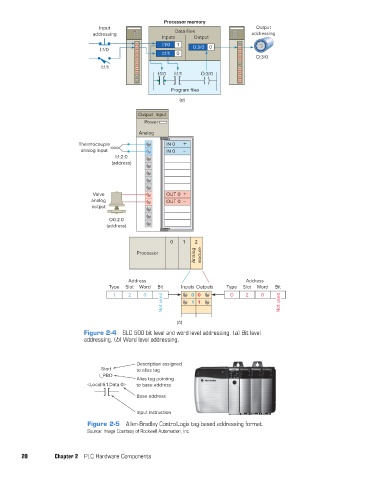
Input                Processor memory              Output
                                       addressing                Data files                addressing
                                                             Inputs    Output
                                                             I:1/0  1
                                         I:1/0                         0:3/0  0
                                                             I:1/1  0
                                                                                            O:3/0
                                         I:1/1
                                                            I:1/0  I:1/1  O:3/0

                                                                Program files
                                                                   (a)

                                                     Output  Input
                                                       Power
                                                      Analog
                                  Thermocouple                IN 0  +
                                   analog input               IN 0  –
                                              I:1:2:0
                                             (address)


                                       Valve                  OUT 0  +
                                      analog                  OUT 0  –
                                      output
                                            O0:2.0
                                           (address)

                                                                0   1   2
                                                                        Analog  module
                                                     Processor


                                                  Address                               Address
                                            Type  Slot  Word  Bit  Inputs Outputs  Type  Slot  Word  Bit
                                             I    2    0               0 0         O    2    0
                                                             Not used  1 1                         Not used


                                                                  (b)
                                    Figure 2-4  SLC 500 bit level and word level addressing. (a) Bit level
                                    addressing. (b) Word level addressing.


                                                     Description assigned
                                         Start       to alias tag
                                         I_PBO
                                                     Alias tag pointing
                                     <Local:6:1.Data.0>  to base address
                                                     Base address

                                                     Input instruction

                                     Figure 2-5  Allen-Bradley ControlLogix tag-based addressing format.
                                     Source: Image Courtesy of Rockwell Automation, Inc.


               20         Chapter 2  PLC Hardware Components


          pet73842_ch02_017-045.indd   20                                                                               03/11/15   3:43 PM
   34   35   36   37   38   39   40   41   42   43   44