Page 40 - Programmable Logic Controllers, Fifth Edition Mobile 2
P. 40

Mixer_motor
                                      I:1      I:1    O:2           Pressure_switch  Temperature_switch  <Local:2:0.Data.1>
                                                                                  <Local:1:I.Data.2>
                                                                    <Local:1:I.Data.1>
                                        1       2      1
                                                                           Manual_pushbutton
                                          I:1                               <Local:1:I.Data.3>
                                           3
                                (a) SLC 500 rack/slot-based addressing  (b) Equivalent ControlLogix 5000 tag-base addressing
                                Figure 2-6  Rack/slot-based versus tag-based addressing.


                     PC-based control runs on personal or industrial hard-
                   ened computers. Also known as soft PLCs, they simulate
                   the functions of a PLC on a PC, allowing open architecture
                   systems to replace proprietary PLCs. This implementa-
                   tion uses an input/output card (Figure 2-7) in conjunction
                   with the PC as an interface for the field devices.
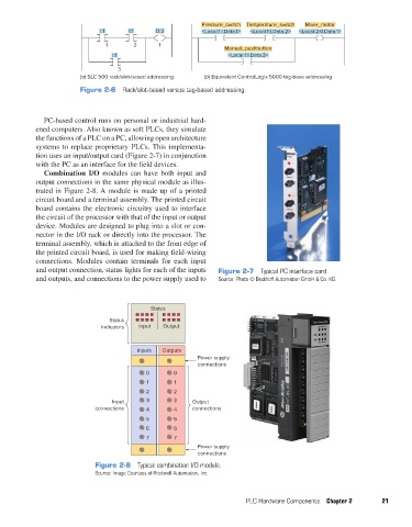
                     Combination I/O modules can have both input and
                   output connections in the same physical module as illus-
                   trated in Figure 2-8. A module is made up of a printed
                   circuit board and a terminal assembly. The printed circuit
                   board contains the electronic circuitry used to interface
                   the circuit of the processor with that of the input or output
                   device. Modules are designed to plug into a slot or con-
                   nector in the I/O rack or directly into the processor. The
                   terminal assembly, which is attached to the front edge of
                   the printed circuit board, is used for making field-wiring
                   connections. Modules contain terminals for each input
                   and output connection, status lights for each of the inputs   Figure 2-7  Typical PC interface card.
                   and outputs, and connections to the power supply used to   Source: Photo © Beckhoff Automation GmbH & Co. KG.


                                                     Status
                                         Status
                                      indicators  Input  Output


                                                 Inputs  Outputs
                                                                   Power supply
                                                                   connections
                                                    0       0
                                                    1       1
                                                    2       2
                                          Input     3       3    Output
                                     connections    4       4    connections
                                                    5       5
                                                    6       6
                                                    7       7
                                                                   Power supply
                                                                   connections
                                     Figure 2-8  Typical combination I/O module.
                                     Source: Image Courtesy of Rockwell Automation, Inc.


                                                                                 PLC Hardware Components  Chapter 2      21


          pet73842_ch02_017-045.indd   21                                                                               03/11/15   3:43 PM
   35   36   37   38   39   40   41   42   43   44   45