Page 42 - Programmable Logic Controllers, Fifth Edition Mobile 2
P. 42

Power             Backplane power
                                                                                  supply
                      Indicator  Signaling      Relays       Motor
                       lights    column                      starter


                                       Discrete outputs


                                       Discrete inputs                   Figure 2-12  Modules receive their voltage and current
                                                                         from the backplane.


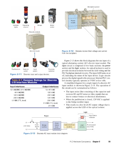
                                                                           Figure 2-13 shows the block diagrams for one input of a
                                                                         typical alternating current (AC) discrete input module. The
                                                                         input circuit is composed of two basic sections: the power
                                                                         section and the logic section. An optical isolator is used to
                     Pushbuttons  Selector  Limit          Proximity
                                 switch    switch          switches      provide electrical isolation between the field wiring and the
                                                                         PLC backplane internal circuitry. The input LED turns on or
                   Figure 2-11  Discrete input and output devices.
                                                                         off, indicating the status of the input device. Logic circuits
                                                                         process the digital signal to the processor. Internal PLC con-
                     Table 2-1 Common Ratings for Discrete               trol circuitry typically operates at 5 VDC or less volts.
                     I/O Interface Modules                                 A simplified diagram for a single input of a discrete AC
                                                                         input module is shown in Figure 2-14. The operation of
                   Input Interfaces                  Output Interfaces
                                                                         the circuit can be summarized as follows:
                   12 V AC/DC /24 V AC/DC               12–48 V AC
                       48 V AC/DC                         120 V AC         •  The input noise filter consisting of the capacitor and
                      120 V AC/DC                         230 V AC           resistors R1 and R2 removes false signals that are
                      230 V AC/DC                         120 V DC           due to contact bounce or electrical interference.
                     5 V DC (TTL level)                   230 V DC         •  When the pushbutton is closed, 120 VAC is applied
                                                      5 V DC (TTL level)     to the bridge rectifier input.
                                                           24 V DC         •  This results in a low-level DC output voltage that is
                                                                             applied across the LED of the optical isolator.

                                                                                                Logic

                                                      Power                                          Input status
                                                                                                     indicator

                                   L1                             Zener
                                             Input  Bridge        diode     Opto-electrical  Logic  To processor
                                 (120 VAC)   signal  rectifier     level       isolation    circuits  (low VDC)
                                   L2                           detection

                                 Figure 2-13  Discrete AC input module block diagram.


                                                                                 PLC Hardware Components  Chapter 2      23


          pet73842_ch02_017-045.indd   23                                                                               03/11/15   3:43 PM
   37   38   39   40   41   42   43   44   45   46   47