
Page 80 - Programmable Logic Controllers, Fifth Edition
P. 80
4
Fundamentals of Logic
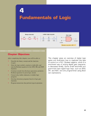
Relay schematic Ladder logic program
Gate logic
LS1 LS2 SOL A B Y A
Y
LS1 LS2 SOL B Output
Inputs
Boolean equation: AB = Y
Chapter Objectives
After completing this chapter, you will be able to: This chapter gives an overview of digital logic
gates and illustrates how to duplicate this type
• Describe the binary concept and the functions
of gates of control on a PLC. Boolean algebra, which is a
• Draw the logic symbol, construct a truth table, and shorthand way of writing digital gate diagrams,
state the Boolean equation for the AND, OR, and NOT is discussed briefly. Some small hand-held pro-
functions grammers have digital logic keys, such as AND,
• Construct circuits from Boolean expressions and derive OR, and NOT, and are programmed using Bool-
Boolean equations for given logic circuits ean expressions.
• Convert relay ladder schematics to ladder logic
programs
• Develop elementary programs based on logic gate
functions
• Program instructions that perform logical operations
61
pet73842_ch04_061-073.indd 61 03/11/15 3:52 PM