Page 82 - Programmable Logic Controllers, Fifth Edition
P. 82

Hardwired circuit
                                                                        Truth table                Logic representation
                                  SW-A  SW-B
                                                               SW- A     SW- B      Light      SW-A               Light
                                                               Open  (0)  Open  (0)  O  (0)
                                                  Light        Open  (0)  Closed (1)  O  (0)
                                                               Closed (1)  Open  (0)  O  (0)
                                                               Closed (1)  Closed (1)  On (1)  SW-B


                        Figure 4-5  AND logic gate operates similarly to control devices connected in series.


                   illustrates the four possible combinations of inputs for a   0
                   2-input AND gate. The basic rules that apply to an AND   A                 Output (Y )  =  0
                   gate are:                                               B  0

                     •  If all inputs are 1, the output will be 1.            0
                     •  If any input is 0, the output will be 0.           A                                   Truth table
                                                                              1               Output (Y )  =  1  Inputs  Output
                     The  AND logic gate operates similarly to control     B                                  A   B   Y
                   devices connected in series, as illustrated in Figure 4-5.                                 0   0   0
                   The light will be on only when both switch A and switch   A  1                             0 1  0 1  1 1
                   B are closed.                                              0               Output (Y )  =  1  1  1  1
                                                                           B
                   The OR Function
                                                                              1
                   The symbol drawn in Figure 4-6 is that of an OR gate. An   A
                   OR gate can have any number of inputs but only one out-  B  1              Output (Y )  =  1
                   put. The OR gate output is 1 if one or more inputs are 1.
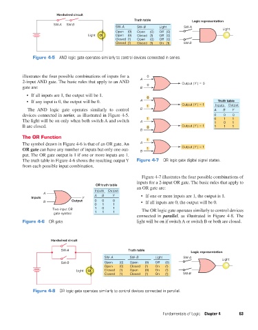
                   The truth table in Figure 4-6 shows the resulting output Y   Figure 4-7  OR logic gate digital signal states.
                   from each possible input combination.

                                                                           Figure 4-7 illustrates the four possible combinations of
                                                                         inputs for a 2-input OR gate. The basic rules that apply to
                                                      OR truth table
                                                     Inputs  Output      an OR gate are:
                             A
                       Inputs                  Y     A   B    Y            •  If one or more inputs are 1, the output is 1.
                             B            Output     0   0    0            •  If all inputs are 0, the output will be 0.
                                                     0   1    1
                                 Two-input OR        1   0    1            The OR logic gate operates similarly to control devices
                                  gate symbol        1   1    1
                                                                         connected in  parallel, as illustrated in Figure 4-8. The
                   Figure 4-6  OR gate.                                  light will be on if switch A or switch B or both are closed.


                                Hardwired circuit

                                     SW-A                            Truth table
                                                                                                   Logic representation
                                                          SW- A       SW- B       Light        SW-A              Light
                                     SW-B                 Open   (0)  Open   (0)  O    (0)
                                                          Open   (0)  Closed  (1)  On  (1)
                                            Light         Closed  (1)  Open  (0)  On   (1)
                                                          Closed  (1)  Closed  (1)  On  (1)    SW-B


                        Figure 4-8  OR logic gate operates similarly to control devices connected in parallel.


                                                                                     Fundamentals of Logic  Chapter 4    63


          pet73842_ch04_061-073.indd   63                                                                               03/11/15   3:52 PM
   77   78   79   80   81   82   83   84   85   86   87