
Page 81 - Programmable Logic Controllers, Fifth Edition
P. 81
4.1 The Binary Concept
the outcome and a symbol that represents the operation.
For the purpose of this discussion, the outcome or out-
The PLC, like all digital equipment, operates on the binary put is called Y and the signal inputs are called A, B, C,
principle. The term binary principle refers to the idea that and so on. Also, binary 1 represents the presence of a
many things can be thought of as existing in only one of signal or the occurrence of some event, and binary 0
two states. These states are 1 and 0. The 1 and 0 can rep- represents the absence of the signal or nonoccurrence
resent ON or OFF, open or closed, true or false, high or of the event.
low, or any other two conditions. The key to the speed and
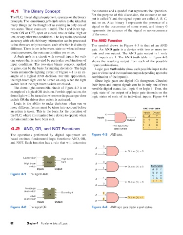
accuracy with which binary information can be processed The AND Function
is that there are only two states, each of which is distinctly The symbol drawn in Figure 4-3 is that of an AND
different. There is no in-between state so when informa- gate. An AND gate is a device with two or more in-
tion is processed the outcome is either yes or no. puts and one output. The AND gate output is 1 only
A logic gate is a circuit with several inputs but only if all inputs are 1. The AND truth table in Figure 4-3
one output that is activated by particular combinations of shows the resulting output from each of the possible
input conditions. The two-state binary concept, applied input combinations.
to gates, can be the basis for making decisions. The high Logic gate truth tables show each possible input to the
beam automobile lighting circuit of Figure 4-1 is an ex- gate or circuit and the resultant output depending upon the
ample of a logical AND decision. For this application, combination of the input(s).
the high beam light can be turned on only when the light Since logic gates are digital ICs (Integrated Circuits)
switch AND the high beam switch are closed. their input and output signals can be in only one of two
The dome light automobile circuit of Figure 4-2 is an possible digital states, i.e., logic 0 or logic 1. Thus, the
example of a logical OR decision. For this application, the logic state of the output of a logic gate depends on the
dome light will be turned on whenever the passenger door logic states of each of its individual inputs. Figure 4-4
switch OR the driver door switch is activated.
Logic is the ability to make decisions when one or
more different factors must be taken into account before AND truth table
an action is taken. This is the basis for the operation of Inputs Output
the PLC, where it is required for a device to operate when A A B Y
certain conditions have been met. Inputs Y 0 0 0
B Output
0 1 0
Two-input AND 1 0 0
4.2 AND, OR, and NOT Functions gate symbol 1 1 1
The operations performed by digital equipment are Figure 4-3 AND gate.
based on three fundamental logic functions: AND, OR,
and NOT. Each function has a rule that will determine
0
A
Output (Y ) = 0
0
B
Light switch
High beam
High beam AND light A 0
switch Output (Y ) = 0 Truth table
Inputs Output B 1 A B Y
Figure 4-1 The logical AND. 0 0 1 0
0
0
1
A 1 0 0
Output (Y ) = 0 1 1 1
0
B
Passenger
door switch Dome light
OR A 1
Driver Output (Y ) = 1
door switch 1
Inputs Output B
Figure 4-2 The logical OR. Figure 4-4 AND logic gate digital signal states.
62 Chapter 4 Fundamentals of Logic
pet73842_ch04_061-073.indd 62 03/11/15 3:52 PM