
Page 111 - Programmable Logic Controllers, Fifth Edition - Mobile version
P. 111
edit status, and whether forces are present and
enabled.
- Project Window—This window displays the file
folders listed in the project tree.
- Project Tree—The project tree is a visual repre-
sentation of all folders and their associated files
contained in the current project. From the project
tree, you can open files, create files, modify file
parameters, copy files, hide or unhide files, delete
files, and rename files.
- Result Window—This window displays the re-
sults of either a search or a verify operation. The
verify operation is used to check the ladder pro-
gram for errors.
- Active Tab—This tab identifies which program is
currently active. Figure 5-49 I/O configuration screen.
- Status Bar—This bar contains information rel- Source: Image Courtesy of Rockwell Automation, Inc.
evant to the current file.
- Split Bar—The split bar is used to split the ladder the different processors that the RSLogix software
window to display two different program files or can program. You simply scroll down the list until
groups of ladder rungs. you find the processor you are using and select it.
- Tabbed Instruction Toolbar—This toolbar displays
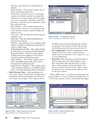
the instruction set as a group of tabbed categories. • I/O Configuration—The I/O Configuration screen
- Instruction Palette—This tool contains all the (Figure 5-49) lets you click or drag-and-drop a
available instructions displayed in one table to module from an all-inclusive list to assign it to a slot
make the selection of instructions easier. in your configuration.
- Ladder Window—This window displays the cur- • Data Files—Data File screens contain data that are
rently open ladder program file and is used to used in conjunction with ladder program instruc-
develop and edit ladder programs. tions and include input and output files as well as
- Ladder Window Properties—This window allows timer, counter, integer, and bit files. Figure 5-50
you to change the display of your ladder program shows an example of the bit file B3, which is used
and its associated addressing and documentation. for internal relays. Note that all the addresses from
• Select Processor Type—The programming soft- this file start with B3.
ware needs to know what processor is being used in Relay ladder logic is a graphical programming lan-
conjunction with the user program. The Select Pro- guage designed to closely represent the appearance of
cessor Type screen (Figure 5-48) contains a list of a wired relay system. It offers considerable advantages
Figure 5-48 Select processor type screen. Figure 5-50 Data bit file B3 screen.
Source: Image Courtesy of Rockwell Automation, Inc. Source: Courtesy of TheLearningPit.
92 Chapter 5 Basics of PLC Programming
pet73842_ch05_074-097.indd 92 05/11/15 4:18 PM