Page 113 - Programmable Logic Controllers, Fifth Edition - Mobile version
P. 113

(a) Digital signal  (b) Analog signal                                 Analog output
                                                                        Valve
                                                                                     Level sensor

                          Analog      ADC     Binary                                                          PLC
                                                                                                              Analog I/O
                          signal              output                                                          Module
                          input                       10 01 1                                     Processor
                                                                                                                 Level
                                                                                                                 Preset
                           (c) Analog-to-digital converter (ADC)
                                                                                                                 Point
               Figure 5-53  Digital and analog signals.
                                                                                              Analog input

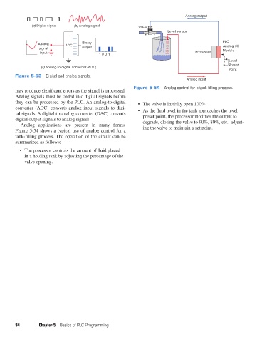
                                                                     Figure 5-54  Analog control for a tank-filling process.
               may produce significant errors as the signal is processed.
               Analog signals must be coded into digital signals before
               they can be processed by the PLC. An analog-to-digital   •  The valve is initially open 100%.
               converter (ADC) converts analog input signals to digi-
               tal signals. A digital-to-analog converter (DAC) converts   •  As the fluid level in the tank approaches the level
               digital output signals to analog signals.                  preset point, the processor modifies the output to
                  Analog applications are present in many forms.          degrade, closing the valve to 90%, 80%, etc., adjust-
               Figure 5-54 shows a typical use of analog control for a    ing the valve to maintain a set point.
               tank-filling process. The operation of the circuit can be
               summarized as follows:
                 •  The processor controls the amount of fluid placed
                    in a holding tank by adjusting the percentage of the
                    valve opening.


               94         Chapter 5  Basics of PLC Programming


          pet73842_ch05_074-097.indd   94                                                                               05/11/15   4:18 PM
   108   109   110   111   112   113   114   115   116   117   118